How Are Exhaust Manifolds Made: Genius Essential
Exhaust manifolds are primarily made using the precise process of cast iron or stainless steel fabrication, often involving advanced casting or tubular welding techniques to ensure they withstand extreme engine heat, manage toxic gases effectively, and boost engine performance.

Dorman
Dorman 674-418 Exhaust Manifold Kit - Includes…
- Ideal replacement - this exhaust manifold was precision-engineered and durably manufactured to match the fit and function of the s…
- Reliable construction - durable materials resist warping, cracking and leaking for long-lasting performance
- Complete repair - includes all necessary gaskets and downpipe hardware
As an Amazon Associate I earn from qualifying purchases.
Welcome! If you’ve ever wondered where that gritty, donut-shaped piece of metal bolted right onto your engine comes from, you’re not alone. The exhaust manifold sounds complicated, but it’s a vital part that handles hot, poisonous engine gases. When it cracks or leaks, it messes with your car’s performance, causing strange noises or a dip in power. It’s frustrating when essential components have complex origins. Good news! We’re going to break down exactly how these essential parts are manufactured, step-by-step, using simple terms. By the end of this guide, you’ll understand the genius behind the metal. Let’s dive into the creation of the exhaust manifold!
The Exhaust Manifold: Why Its Creation Matters for Your Ride
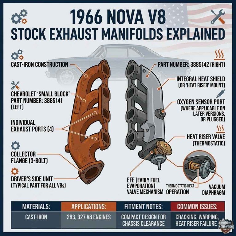
The exhaust manifold is the very first part of your car’s exhaust system. It bolts directly to the cylinder head of your engine. Its main job is simple: collect hot, dirty gases from each cylinder and smoothly merge them into one exit pipe.
Because this component lives closest to the engine, it faces extreme temperatures—sometimes reaching over 1,600°F! This harsh environment demands a very specific, durable manufacturing process. If it fails, engine backpressure can increase, hurting fuel economy and power. Understanding how durable manifolds are made gives you appreciation for quality replacements.
Two Main Types of Manifolds and Their Manufacturing Paths
Manufacturers use two primary methods based on the manifold design required. Understanding these allows you to see where cost and performance differences come from.
1. Cast Iron Manifolds: The Workhorse Method
Most OEM (Original Equipment Manufacturer) manifolds found on everyday vehicles are made from cast iron. This is a budget-friendly, durable material capable of handling high heat without deformation.
Step 1: Creating the Pattern and Mold
The process begins by designing a physical pattern of the finished manifold. This pattern is usually made from wood or metal and serves as the negative space for the mold.
- Pattern Creation: Engineers design the exact shape, making sure to slightly oversize it to account for metal shrinkage during cooling.
- Mold Making (Greensand Casting): For mass production, a mixture of sand, clay, and water (greensand) is tightly packed around the pattern inside a metal frame called a flask.
- Pattern Removal: The pattern is carefully drawn out of the compacted sand, leaving an exact cavity—the mold—where the molten iron will flow.
For complex, high-volume parts, high-pressure mold systems (using resin-bonded sand) may be used for greater detail accuracy.
Step 2: Pouring the Molten Iron
The raw material, gray cast iron, is heated in a furnace until it becomes a flowing liquid. This requires precise temperature control.
- The molten iron is analyzed to ensure the carbon and silicon content is correct for heat resistance and strength.
- The liquid iron is poured carefully into the sand molds through designated openings (gates and risers).
- Risers are included to fill any voids created as the metal contracts while cooling.
Step 3: Cooling and Shakeout
Once poured, the metal must cool slowly enough to avoid cracking but fast enough for production schedules. This cooling happens right inside the sand mold.
After cooling, the mold is broken open—this is called the “shakeout.” The raw manifold casting is freed from the sand.
Step 4: Finishing and Machining
The rough casting still has excess metal (flash) and rough surfaces that need cleaning up. This is where the part becomes ready to seal against the engine head.
- Cleaning and Tumbling: The manifold is cleaned to remove residual sand.
- Grinding and Blasting: Power tools and abrasive blasting clean the exterior surfaces.
- Precision Machining: The most critical step! The mating surface—the face that seals against the cylinder head—must be perfectly flat. Specialized CNC (Computer Numerical Control) machines precisely mill this surface to ensure a leak-proof seal. Check out resources on precision machining tolerances often used in aerospace and automotive industries for reference on necessary accuracy (e.g., NIST guidelines on tolerances).
2. Tubular or Tubular Stainless Steel Headers: The Performance Choice
Performance manifolds, often called headers, are constructed from individual tubes that are welded together. These are usually made from stainless steel because it handles high heat expansion better and reduces weight compared to cast iron.
Step 1: Tube Sourcing and Bending
Unlike casting, header construction starts with pre-fabricated tubes. These tubes must be precise, often using mandrel bending.
Mandrel Bending Explained: For performance, the inside diameter (ID) of the tube must remain consistent throughout a bend. If standard roll-bending is used, the inside of the bend collapses, reducing flow. Mandrel bending involves placing a flexible internal support (the mandrel) inside the tube during the bending process. This prevents unwanted crimps or wall thinning.
The tubes are bent to specific lengths and angles dictated by the engine’s firing order to equalize exhaust pulse timing—a key factor in engine scavenging (pulling exhaust out faster).
Step 2: Port Merging and Collector Fabrication
Once the individual runners (tubes) are bent, they must be joined to merge the gases smoothly.
- Port Flange Attachment: Each tube is welded to a flat metal plate called the collector flange. This flange has holes drilled to match the engine ports.
- Welding the Runners: The expert welder joins the tubes together at the “collector,” ensuring smooth internal transitions. On equal-length headers, the tubes are carefully measured so that the path length from the exhaust valve to the collector outlet is nearly identical for every cylinder.
- Welding Techniques: High-quality headers frequently use TIG (Tungsten Inert Gas) welding. TIG welding is slower but produces incredibly strong, clean, and aesthetically pleasing welds that resist cracking under thermal stress.
Step 3: Adding External Components and Finishing
After the main structure is welded, supporting pieces are added.
- Support Brackets: Brackets are welded on to help support the weight of the header and prevent vibration from cracking the welds near the engine block.
- O2 Sensor Bungs: Bungs (threaded ports) for oxygen sensors are welded right into the appropriate locations within the runners.
- Surface Treatment: Stainless steel headers are often polished, bead-blasted, or coated (like ceramic coating) to improve durability, appearance, and heat retention. Ceramic coatings help keep heat inside the header, which speeds up the exhaust gas flow—improving performance.

Comparing Manufacturing Materials Used in Exhaust Manifolds
The choice between cast iron and stainless steel headers dramatically affects the manufacturing route, cost, and longevity. Here is a quick comparison of the materials commonly used.
| Feature | Cast Iron (Common OEM) | Stainless Steel (Common Header) |
|---|---|---|
| Primary Process | Casting (Sand Mold) | Tubular Welding (Mandrel Bending) |
| Heat Resistance | Very Good (Bulky material slows heat transfer) | Excellent (Thin walls heat up and cool down fast) |
| Weight | Heavy | Lighter |
| Performance Goal | Durability and Cost Efficiency | Optimized Flow and Scavenging |
| Corrosion Resistance | Poor (Prone to rust if coating fails) | Excellent |
Quality Control: Checking the Genius of the Manufacture
Manufacturing these parts is only half the battle; ensuring they don’t fail under the hood is crucial. Quality assurance protocols are intense, especially for high-mileage vehicles.
Casting Inspection Checkpoints
Inspecting a cast iron manifold focuses heavily on structural integrity before it ever sees the road:
- Dimensional Checks: Using coordinate measuring machines (CMM) to verify the bolt pattern alignment and flange flatness are within micron tolerances.
- X-Ray/Ultrasonic Testing: Non-destructive testing methods look inside the casting for hidden voids, cracks, or sand inclusions that could become failure points under heat cycles.
- Pressure Testing: Finished castings are sometimes plugged and pressurized with air or water to check for porosity leaks—especially important on water-cooled exhaust manifolds found in some marine or heavy-duty applications.
Header Inspection Checkpoints
For tubular stainless steel headers, quality control centers on weld integrity and flow characteristics:
- Weld Penetration Check: Every critical weld joint is visually inspected or sometimes dye-penetrant tested to ensure full fusion and no signs of cracking near the joints. A weak weld is the number one failure point on a cheap header.
- Runner Length Verification: Using tape measures or digital scanners to confirm that the lengths of the runners match the design goals for performance tuning.
- Fitment Testing: The final set is physically bolted onto a known good engine block to verify the clearance around steering components, oil filters, and O2 sensor access points.
The Final Step: Surface Treatment and Coating
Once the raw manifold or header passes final inspection, it heads to the finishing line to maximize its life span and performance characteristics.
For Cast Iron Manifolds
Since cast iron rusts easily, it needs protection. This is usually achieved through either painting or specialized coating:
- High-Temperature Paint: A coat of special heat-resistant paint is applied. This paint keeps the raw iron from rusting immediately but will often burn off or change color once the engine reaches operating temperature for the first time.
- Ceramic Coating (Advanced): Higher-end cast manifolds might receive a thin ceramic coating to help manage heat near the engine bay, although this is more common on performance headers.
For Stainless Steel Headers
Stainless steel resists oxidation naturally, but coatings provide huge thermal benefits, especially for performance gains.
Ceramic Coating Application: This involves cleaning the metal thoroughly, spraying on a base layer, and then baking the part in a high-temperature oven (often over 400°F) to cure the ceramic particles onto the metal surface. This hard coating ensures that the heat pulse stays inside the tube, improving exhaust velocity. This process is often outsourced to specialized coater shops due to the complexity of the high-temperature curing cycle.
Understanding the Manufacturing Choices: Why Should You Care?
As a car owner, knowing how these parts are made helps you make better choices when you need a replacement. Here’s a quick breakdown of what the manufacturing method implies for your wallet and your driving.
When Cast Iron Manufacturing Wins
If you are replacing a factory part on a daily driver that sees standard city and highway miles, the longevity of a well-made cast iron manifold is hard to beat for the price. The casting process is scalable and efficient, keeping replacement costs lower.
When Tubular Welding Manufacturing Wins
If your goal is towing, track use, or simply getting the absolute best throttle response, the precision required for TIG-welded stainless steel headers is worth the investment. The manufacturer has spent time ensuring the path length is perfect, maximizing the pulse effect of the exhaust pulses.
This optimization is why performance shops invest heavily in R&D for header design. They are essentially creating a tuned instrument for the engine’s breathing. You can learn more about engine flow dynamics and how exhaust timing affects overall performance from reputable academic engineering studies on fluid dynamics in internal combustion engines.
Frequently Asked Questions (FAQ) About Exhaust Manifold Creation
Here are fast answers to common beginner questions about how these parts are built and what they are made of.
Q1: Is making an exhaust manifold dangerous for the workers?
A: Yes, the process involves significant hazards. Workers deal with extremely hot molten metal (over 2,500°F for iron), fine silica dust from sand molds, and powerful grinding/welding fumes. Safety gear and excellent ventilation systems are legally required and absolutely essential in these manufacturing facilities.
Q2: Why do aftermarket headers look so shiny compared to my stock manifold?
A: Stock manifolds are often cast iron coated in dark paint for rust protection. Aftermarket headers are typically stainless steel, polished or ceramic coated. The coating serves two functions: it resists high heat discoloration better than bare metal and, in the case of ceramic coating, it keeps exhaust gases hotter for better flow.
Q3: Can a manifold be repaired once it cracks?
A: For cast iron, welding a crack is very difficult due to the high carbon content, which makes the metal brittle. It often requires specialized pre-heating and welding techniques, and the repair rarely lasts long. For stainless steel headers, high-quality TIG welding is usually effective if the crack is caught early.
Q4: What is the difference between a manifold and a header?
A: Functionally, they do the same job—collect exhaust. Technically, a manifold is typically a thick, cast-iron unit designed mainly for durability. A header (or header manifold) is a performance-oriented assembly made from individual tuned tubes welded together, usually stainless steel, designed for optimal exhaust gas flow.
Q5: How long should an exhaust manifold last?
A: A quality, factory-installed cast iron manifold, when kept cool and not subjected to extreme, continuous abuse (like frequent overheating), should easily last the life of the vehicle—150,000 to 200,000 miles or more. Headers, being stainless steel, often last longer if the connection welds hold up.
Q6: Does casting create any waste material?
A: Yes. After the shakeout, manufacturers reclaim the used sand, clean it, and reuse it. Any metal runner gates or risers that are cut off the final casting are melted down and poured back into the furnace for new castings. Manufacturers focus heavily on recycling scrap metal to keep costs down and reduce waste.
Q7: Why are some performance headers painted black instead of coated?
A: Simple paint is a cheaper way to coat a header than ceramic coating. While it initially hides the steel, standard metallic paint burns off rapidly at engine temperatures. It offers minimal real thermal performance benefit compared to specialized ceramic coatings, which are designed to stay bonded at high heat.
The Future of Exhaust Manifold Manufacturing
The basic science of high-temperature metal formation won’t change much, but the approach is becoming smarter and faster. We are seeing manufacturers increasingly turn to advanced manufacturing techniques to improve quality control and reduce material waste.
Additive Manufacturing (3D Printing) Explorations
While massive engine components like manifolds aren’t yet mass-produced using 3D metal printing (additive manufacturing) due to cost and size limitations, this technology is heavily used for testing and prototyping. Engineers can rapidly prototype new header runner designs, print small sections, and test flow characteristics virtually or in a lab environment much faster than traditional tooling allows. This speeds up the R&D required to create the next generation of high-efficiency exhaust systems.
Advanced Material Science
Manufacturers are not stopping at 304 or 316 stainless steel. Research continues into high-nickel alloys and specialized high-silicon moly irons that can handle even higher cyclic temperatures without developing micro-fractures. These advancements mean future manifolds will be thinner, lighter, and even more durable.
The manufacturing of an exhaust manifold—whether it’s the simple, robust sand casting of an OEM part or the highly complex, precise TIG welding of a performance header—is a true testament to industrial engineering. It requires controlling temperatures hotter than lava and ensuring tolerances tighter than a fine watch to keep your car running smoothly and safely. You now know the journey that metal takes, transforming from raw material into that essential, heat-beaten component bolted to your engine head.
Armed with this knowledge, you can approach your next exhaust repair or upgrade with confidence, knowing exactly what quality looks and feels like. Remember, the right part, made the right way, ensures great performance for miles to come!
Related pick: Check today's price on Amazon