Exhaust Manifold Size Chart by Engine Family
Choose the manifold by engine family and head casting, then verify port spacing, bolt pattern, and outlet location against the OE gasket or flange drawing. One mismatch means it is wrong. Miss that fitment, and you get leaks, cracked flanges, wasted parts, and a downpipe that will not bolt up. This guide gives an engine-family exhaust manifold size chart plus a quick check list for port spacing, flange layout, and outlet position.
An exhaust manifold collects exhaust gases straight from the engine’s cylinders and sends them into a single pipe. It bolts to the cylinder head, seals each exhaust port, and must match the head’s port shape, bolt pattern, and outlet orientation closely enough to clamp without forcing the joint.
What is an exhaust manifold?


Exhaust manifold versus intake manifold
An exhaust manifold sits on the hot side of the engine. An intake manifold feeds air and fuel into the cylinders. They can look similar in photos, but they do opposite jobs, use different gasket shapes, and face different heat loads, so an intake part should never be used as a fitment guide for the exhaust side.
How the manifold seals to the cylinder head
The sealing surface is the flange that sits against the cylinder head. The gasket bridges the port openings and bolt holes, while the fasteners clamp the flange flat enough to keep exhaust from escaping. If the flange is warped, the ports are offset, or the gasket opening is wrong for the head, the seal usually fails fast.
Exhaust manifold temperatures can reach 1,200°F. That is why gasket material, flange flatness, and heat-cycle retention matter as much as the part number.
Why engine family matters
Engine family matters because manifold fit is driven by the engine code or displacement family, the cylinder count, the head layout, and OEM application differences. Two engines with the same number of cylinders can still use different port spacing, different outlet angles, or different bolt-hole patterns at the head.
Firing order can also affect runner packaging and outlet placement, especially on replacement manifolds that try to serve more than one chassis. A part may look correct from the outside and still miss the head by a few millimeters at the flange, which is enough to cause a leak or a bolt that will not start straight.
Why OEM application differences change fitment
OEM application differences matter because truck, marine, and passenger-car versions of the same family may use different accessory brackets, heat shields, downpipe exits, or cylinder-head castings. Marine engine parts are often organized by brand and application. That is a reminder to match the family first, then the application.
Exhaust manifold fitment chart
Use this matrix as a fitment screen, not as a substitute for the OE gasket or flange drawing. If the port spacing, bolt pattern, or outlet position does not line up with your head and exhaust pipe, reject the manifold even if the casting looks close.
| Engine family | Cylinder count | Port spacing | Bolt pattern notes | Outlet orientation | Gasket type | Common mismatch warning signs |
|---|---|---|---|---|---|---|
| 5.3L V8 family | 8 | Family-specific; verify against OE gasket and head casting | Hole layout can differ by head revision and application | Side or rear exit varies by chassis | Engine-specific multi-port gasket | Ports sit high or low, one bolt starts crooked, outlet misses the Y-pipe |
| 6.2L V8 family | 8 | Do not assume it matches 5.3L spacing | Flange may share a look but not the same pattern | Application-specific outlet angle | Matched gasket for the exact head and manifold style | Gasket openings overhang the ports, rear cylinder ports do not center, heat shield contacts the block |
| 5.7L 350ci V8 family | 8 | Small-block pattern is family dependent across castings | Check bolt-hole spacing before ordering headers or cast replacements | Common rearward or downward outlet variations | Small-block V8 exhaust gasket matched to the head | Flange sits on the gasket edge, studs do not line up, outlet lands off the downpipe centerline |
| 7.4L 454ci V8 family | 8 | Larger-port heads need the correct opening size | Pattern can change with marine or truck application | May exit differently because of packaging clearance | Large-port V8 gasket with correct bolt pattern | Port opening is too small, flange rocks on the head, riser or spacer parts do not sit square |
How to read the table
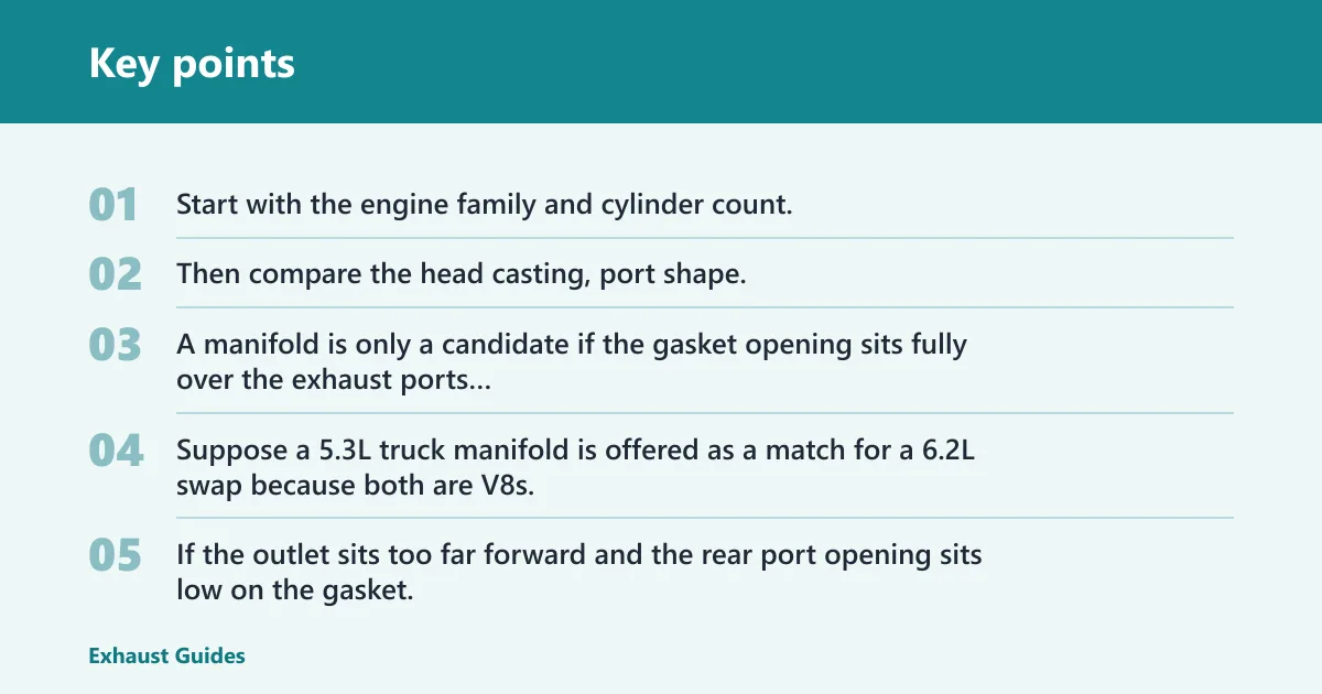
Start with the engine family and cylinder count. Then compare the head casting, port shape, and outlet direction with the part you have in hand. A manifold is only a candidate if the gasket opening sits fully over the exhaust ports and the bolt holes line up without prying the flange into place.
Suppose a 5.3L truck manifold is offered as a match for a 6.2L swap because both are V8s. That is not enough. If the outlet sits too far forward and the rear port opening sits low on the gasket, the pipe will fight the flange and the rear cylinders will be the first place to leak.
How do I measure manifold fitment?
Measure the exhaust ports, the flange, and the gasket together. You are checking port height, port width, center-to-center spacing, bolt hole pattern, and outlet position. If any one of those does not match the head and gasket, the manifold is not a safe install candidate.
Measuring exhaust port height, width, and center spacing
Measure each exhaust port at the cylinder head, not only on the old gasket. Record port height and width, then measure center to center between adjacent ports. Use the old gasket only as a reference if it has not torn or shrunk, and compare it to the new gasket opening size before you assume the manifold is correct.
Checking flange flatness and bolt hole alignment
Lay the flange against a known-flat surface and check for rocking. Then test the bolt holes against the head or a clean gasket without forcing the fasteners. If the bolt pattern is off, the flange thickness or runner entry may be wrong for the head layout, even when the runners themselves look fine.
Confirming gasket opening and stud size
The gasket must match the port opening size and bolt pattern. Material type and heat resistance matter because the joint sees extreme temperature cycling. Fastener checks matter too: confirm bolt size, thread pitch, and stud size before installation, then follow the correct torque specification and recheck heat-cycle retention if the service procedure calls for it.
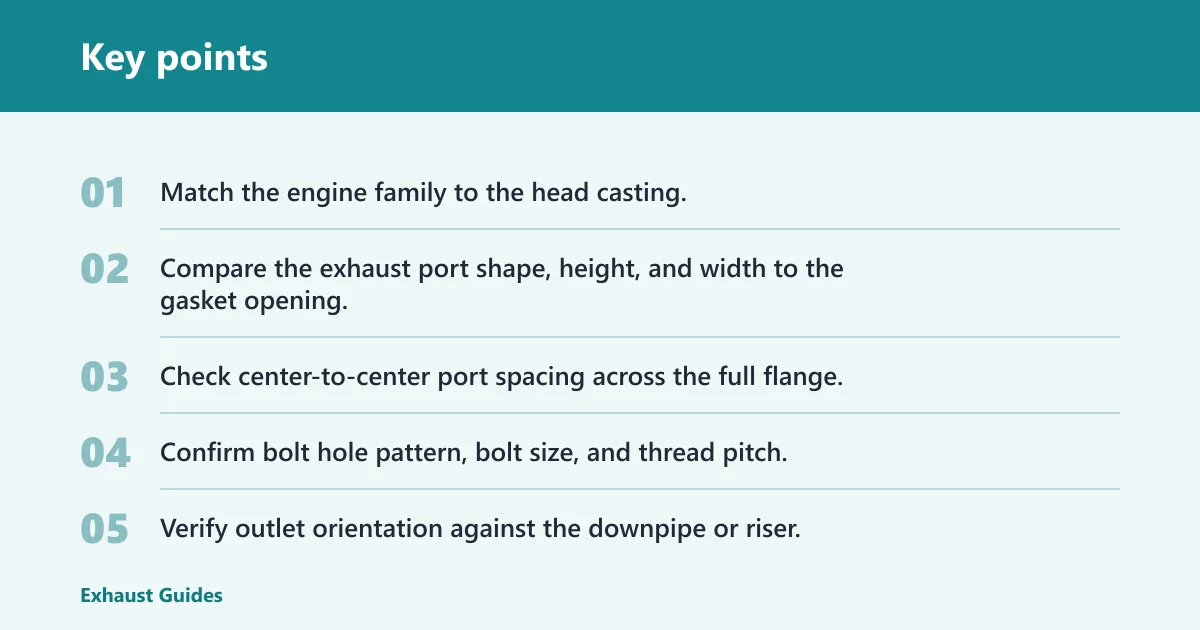
- Match the engine family to the head casting.
- Compare the exhaust port shape, height, and width to the gasket opening.
- Check center-to-center port spacing across the full flange.
- Confirm bolt hole pattern, bolt size, and thread pitch.
- Verify outlet orientation against the downpipe or riser.
- Reject the part if any bolt must be pulled into place.
How do I tell if it matches my head?
A manifold matches the head only when the port shape, port spacing, bolt pattern, and mounting face all align without stress. The gasket should sit fully on the sealing surface, the flange should meet the head evenly, and the outlet should land where the exhaust pipe or riser expects it to land.
Head port shape and mounting face checks
Inspect the cylinder head first. Look for port height, port width, and any shape difference between oval, rectangular, or rounded openings. Then check the mounting face for pitting, carbon tracks, or distortion. A damaged face can make a correct manifold look wrong, and a wrong manifold can look acceptable until the bolts are snugged.
When a close match is still the wrong part
A close-looking part should be rejected if the bolt pattern appears shifted, the runner entry does not center on each port, or the outlet seems to sit at the wrong angle for the pipe. A common first-timer mistake is to accept a manifold because two ports line up while the end ports hang over the gasket edge. That part will usually leak or crack the flange after heat cycles.
Picture a manifold that bolts to three holes on one side but leaves the fourth bolt cocked in the flange. That is not a minor issue. The joint loads unevenly, the gasket crushes on one side, and the leak often shows up as a tap at start-up after the metal expands and contracts.
How do cast iron and tubular manifolds differ by fitment?
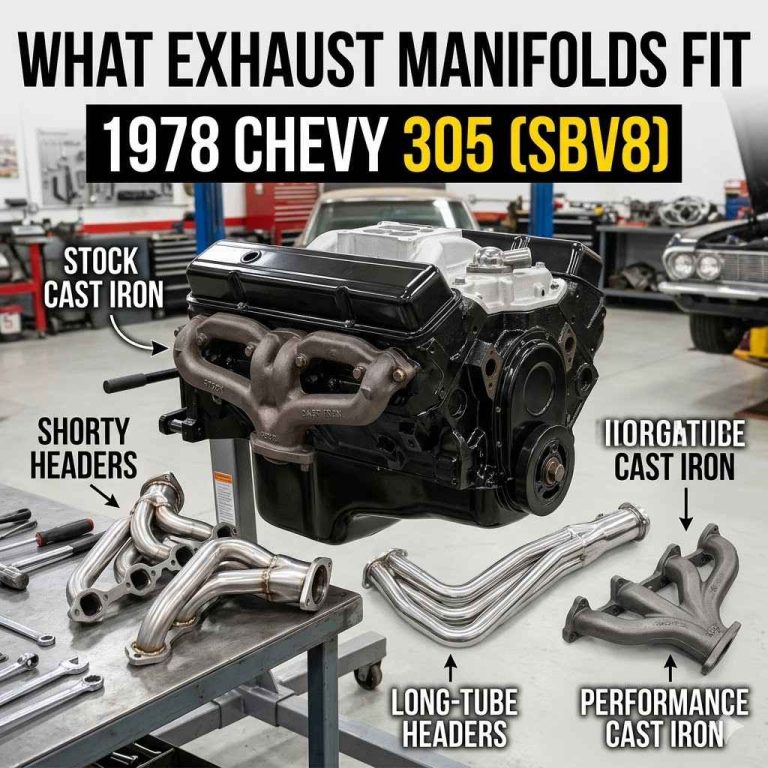
Cast iron and tubular manifolds differ most at the flange, runner shape, and packaging clearance. Cast iron pieces usually track OEM geometry closely, while tubular or header-style replacements may change runner length, diameter, taper, and outlet location. That can improve clearance in one chassis and create a problem in another.
Fitment differences at the flange
Cast iron manifolds often have thicker flanges and more OEM-like bolt patterns, which can help them sit closer to the head with less bracket conflict. Tubular parts may use thinner flanges and welded runner collectors, so flange flatness and runner entry alignment matter more. A slight misalignment at the flange becomes easier to see on a tubular part.
Runner packaging, heat shields, and clearance
Runner length, diameter, shape, and taper affect packaging clearance around steering shafts, frame rails, heat shields, and starter motors. Tubular replacements can leave less room for shields or nearby components. If the part needs a shield to survive in the original location, check that the shield mounting points still line up before installing it.
Cast iron also handles heat differently in packaging terms. A heavy, one-piece casting can be less fussy about collector alignment, but it still must match the head and outlet position. Stainless tubular parts can fit well when they are built for the exact application, yet they are less forgiving of a wrong engine family or a wrong chassis outlet.
What changes after a bad swap?
After a bad swap, the first signs are usually leak symptoms, bolt misalignment, or heat-related interference. A manifold leak can create a ticking or tapping noise on start-up, exhaust smells inside the cabin can point to a leak, and a damaged manifold can reduce fuel efficiency, power, and emissions performance.
Leak symptoms, warped flange signs, and gasket failure
Look for black soot at the flange, a burnt gasket edge, or a flange that loosens after heat cycles. If the flange is warped, the gasket may seal at the center and leak at the ends. If the bolt holes were forced, the leak may start at the side that was pulled hardest against the head.
Common interference points after installation
Check the downpipe or riser connection first. Then check heat shields, O2 sensor placement if applicable, and any bracket that sits near the runner or outlet. A wrong outlet orientation can leave the pipe in a bind even when the manifold bolts to the head, and that stress often shows up as a repeat leak or cracked flange.
One more rule helps in the shop: if the manifold only fits when the bolts are used to steer the part into place, stop. The correct part should line up with the gasket and head before torque is applied. If it needs force, it is not close enough.
Frequently asked questions
What is an exhaust manifold size chart by engine family?
An exhaust manifold size chart by engine family is a fitment table that ties the engine code or displacement family to cylinder count, port spacing, bolt pattern notes, outlet orientation, gasket type, and mismatch warnings. It helps you sort parts before installation, instead of guessing from shape alone.
How do I find the right exhaust manifold for my engine family?
Start with the engine family, then confirm the cylinder head casting, port shape, and outlet direction. Match the manifold to the OE gasket or flange drawing, not just the listing title. If the bolt pattern, port spacing, or outlet location differs, choose another part.
How do I measure exhaust manifold port size and spacing?
Measure the exhaust port height and width at the head, then measure center to center between ports. Compare those numbers to the gasket opening and the manifold flange. If the port openings do not center on the gasket, or if the bolt holes sit off, the part is wrong.
How do I tell if an exhaust manifold matches my head?
It matches when the flange sits flat, the ports center on the head openings, the bolt holes line up without forcing, and the outlet lands where the exhaust pipe expects it. A close visual match is not enough if the gasket edge hangs into the port or the bolts pull sideways.
What is the difference between an exhaust manifold and a header?
An exhaust manifold is usually a shorter, more compact casting or welded assembly that bolts to the head and routes exhaust into a single outlet. A header uses separate runners and a collector. Fitment risk is higher with headers because runner length, collector angle, and packaging clearance matter more.
What causes exhaust manifold leak symptoms after a swap?
Common causes include the wrong gasket opening, misaligned port spacing, a warped flange, incorrect bolt size or thread pitch, and outlet stress from a downpipe that does not line up. A ticking sound on start-up and exhaust smell in the cabin are two common leak clues.
Intake manifold vs exhaust manifold
An intake manifold feeds air and fuel to the cylinders. An exhaust manifold collects gases from the cylinders and sends them into the exhaust system. They are not interchangeable, and the gasket, heat load, bolt pattern, and port shape are different enough that one cannot guide fitment for the other.