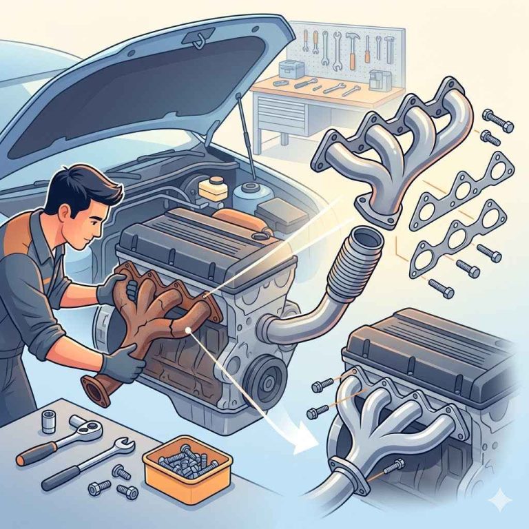
Exhaust Fabrication Guide
Build a custom exhaust by setting tube size from engine output, placing one flex section near the engine, hanging the system at each major mass, and designing every welded section to be removable at one joint. Get that wrong and you buy drone, cracked welds, melted wiring, and a system that blocks clutch, gearbox, or turbo service. This exhaust fabrication guide covers the home-build method, with material, joint, routing, vibration, and service choices for swaps, turbo setups, motorcycles, and street cars.
Start with the system, not the parts list
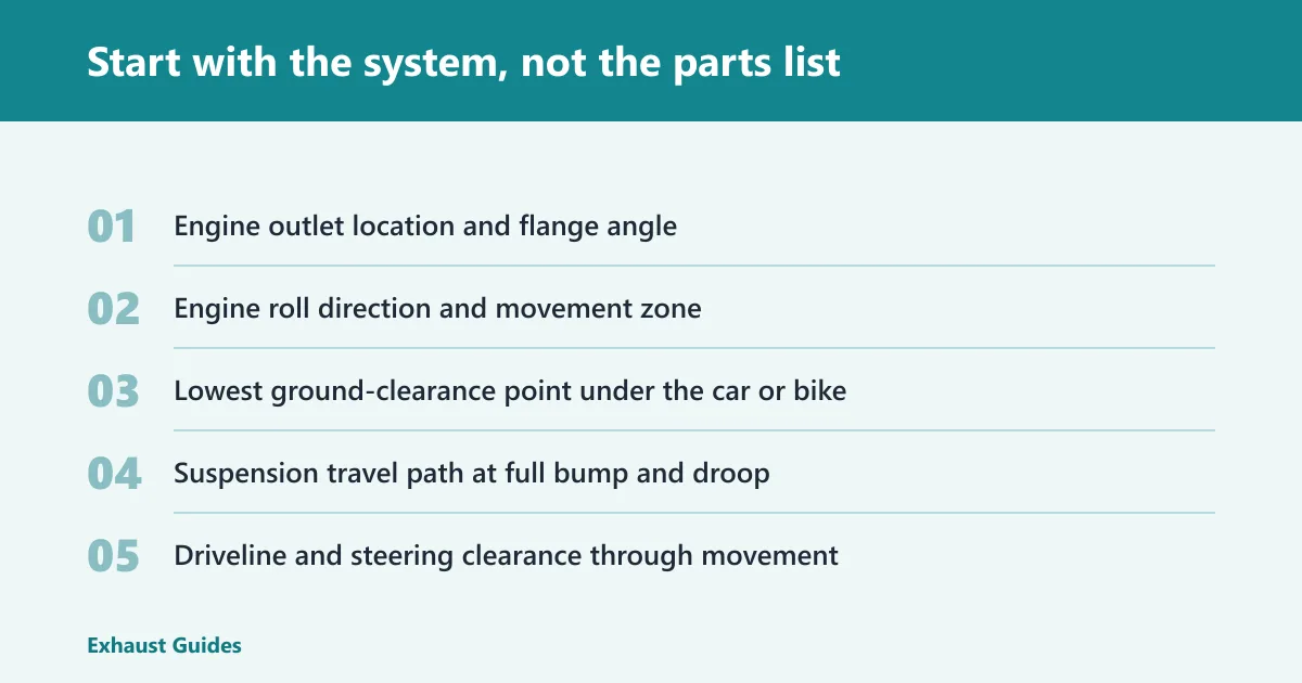


Map movement, packaging, and service before buying tube
Exhaust fabrication, in shop terms, is cutting, fitting, aligning, supporting, and joining tubing into a custom system that clears the engine, chassis, suspension, and ground. Sequence matters more than the catalog. If you buy bends first and route later, you usually end up with bad hanger geometry, poor access, or a flex section trying to cover for weak support.
I start at the engine outlet. Mark where the engine rolls under load, where the transmission moves on its mount, and where the steering shaft, axle, sway bar, and driveshaft pass closest. Then mark heat-sensitive areas: brake lines, wiring, boots, floor pans, fuel lines, and the starter.
Choose separation points early
Every exhaust needs planned break points for removal. On a street car, that may mean a front joint near the head pipe or downpipe, another near the transmission crossmember, and a rear split before the axle or muffler section. On a turbo swap, one modular break near the downpipe saves hours later.
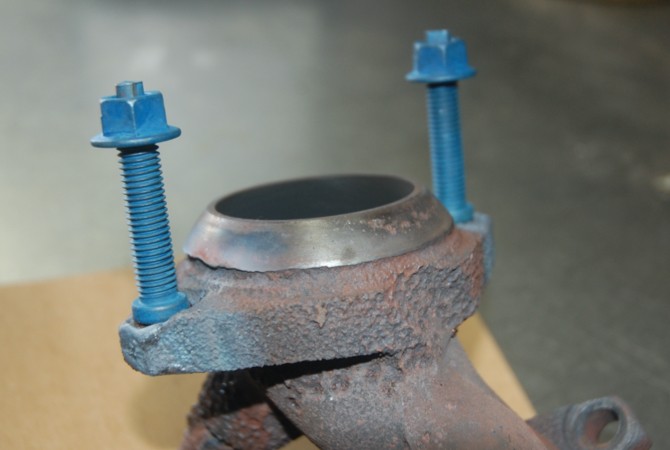
V-bands work well here because they are clamp-based joints with fast service access, but they need clean alignment and enough clamp swing room. Traditional flanges still make sense at some head-pipe connections because fitment is often tied to the engine family or chassis. One major fabrication catalog offers 2-bolt, 3-bolt, and 4-bolt exhaust flanges, which covers most of the usual front-joint formats.
Measurement checklist before the first cut
- Engine outlet location and flange angle
- Engine roll direction and movement zone
- Lowest ground-clearance point under the car or bike
- Suspension travel path at full bump and droop
- Driveline and steering clearance through movement
- Service points for gearbox, clutch, starter, oil filter, and O2 sensors
- Flex coupling position relative to engine movement
- Hanger positions near major masses: catalytic converter, resonator, muffler
- Sensor bung location and clocking
- Tailpipe exit path around bodywork and stance
📊 Lowbrow says custom exhaust building can be done with U-bends and 45-degree bends instead of a tubing bender. Source: Motorcycle Exhaust Fabrication Parts.
How do you fabricate an exhaust system from scratch?
Fabricate an exhaust from scratch by laying out the route first, building it in removable sections, tacking every joint in the vehicle, and final-welding only after clearance, hanger position, and service access are confirmed. The safe sequence is mockup, tack, test-fit, remove, final-weld, leak-check, then recheck movement and heat clearance.
Mock up with reference marks before cutting
Use wire, welding rod, or scrap tube to sketch the centerline path. Mark section breaks with paint pen lines across the tube path so later cuts preserve rotation. This is where the system-first approach pays off. If a joint must rotate for transmission removal, mark that now.
Temporary assembly matters. One supplier organizes exhaust fabrication into tubing, bends, flanges, clamps, hangers, and sensor parts, and that is a useful planning frame because each group affects the next decision. Clamps and slip fits can hold a mockup together while the route is still moving.
Build in sections, not as one long assembly
Break the system into a few logical modules, such as the head pipe or downpipe, mid-pipe, rear section, and tail exit. On swaps, keep the first section short enough to remove around the steering rack or subframe. On motorcycles, routing often has to follow the bike’s frame and stance, and Lowbrow notes that point directly for custom motorcycle exhaust work.
Section building keeps warpage under control and makes it possible to fix a bad cut without remaking the whole system. It also makes leak checking easier.
Tack-weld sequence and final fit
Fit the joints with small, even gaps. Tack at opposing points so the tube cannot pull hard in one direction. Remove the section, add more tacks if needed, reinstall it, and check flange seating, clamp access, sensor access, and hanger preload.
Start final welding only after the whole section has been back in the vehicle, all clamps and flanges seat correctly, the hangers carry the weight without bind, and you can still reach every sensor, fastener, and service point. Reinstall once more after welding, then run a leak check and inspect every close-clearance area under load path and heat path conditions.

Choose tubing by material, diameter, and wall thickness
Material choice in real build terms
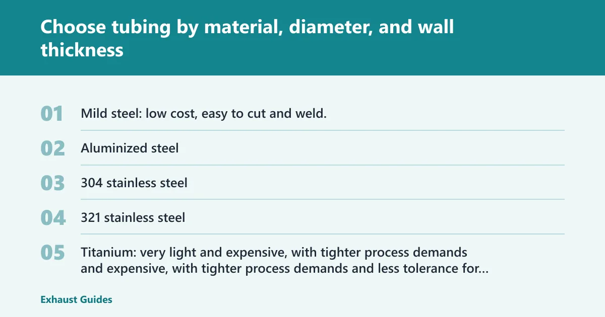
Material changes how the tube welds, how long it lasts in road salt and heat, how much the system weighs, and what a future repair will cost. One catalog lists tubing materials including 304 stainless steel, 321 stainless steel, mild steel, and titanium. Aluminized steel is also common in budget street systems.
- Mild steel: low cost, easy to cut and weld, good for budget builds and mockup-heavy projects, but rust is the tax paid later.
- Aluminized steel: budget-friendly with better corrosion resistance than bare mild steel, but cut edges and weld areas lose some protection.
- 304 stainless steel: the common long-life choice for street and swap builds. It costs more, moves more with heat, and wants better fit-up.
- 321 stainless steel: often picked where sustained heat is high, such as some turbo sections.
- Titanium: very light and expensive, with tighter process demands and less tolerance for poor fit-up.
Diameter should match the engine and the route
Do not buy the biggest pipe that fits under the car. I size pipe from actual power level, rpm band, turbine outlet or collector size, and the room the chassis gives me for bends, hangers, heat shielding, and tools. Oversizing makes routing harder, slows gas velocity in many street combinations, and leaves less room for hangers, shields, and service access.
For home builders, the better question is often, “What size supports the build without forcing a bad route?” I have had smaller tube on a clean path work better than a huge pipe that needed crushed sections, awkward joints, and miserable wrench access.
Wall thickness affects welding and durability
Thin wall saves weight and can look tidy, but it punishes poor heat control. Thick wall resists dents and burn-through better, but it adds weight and takes more heat to join, which can pull flanges and move tacked sections. The right choice depends on material, weld process, and how exposed the system will be to road strikes.
Lowbrow specifies its motorcycle exhaust tubing as 1.75-inch and 16-gauge .063-inch mild carbon steel, and notes that its tubing is ready for MIG or TIG welding. That is a useful reference point for bike builds because motorcycles put the tube in plain view and close to foot controls, frame rails, and lean-angle limits.
How do you build a mandrel bent exhaust without a tubing bender?
A mandrel bent exhaust can be built without a tubing bender by combining straight sections with preformed U-bends and 45-degree bends, cutting them into smaller arcs, and rotating each piece to follow the planned route. The work is slower than one-piece bending, but layout freedom is much better for home fabrication.
Use preformed bends as building blocks
Many home builders never touch a tubing bender. Lowbrow says custom exhaust building can be done with U-bends and 45-degree bends instead of a tubing bender, and that is true for cars as well as motorcycles. Other suppliers split fabrication parts into straight tubing, bends, and joint hardware because that modular approach fits garage work.
Mandrel bends matter because the tube keeps a more consistent internal shape through the turn. In tight packaging, that consistency makes outside clearance and inside flow easier to predict.
Pick centerline radius with packaging in mind
Lowbrow offers U-bends and 45-degree bends in multiple centerline radius options. Smaller radius helps tuck a route above a crossmember or around a frame tube. The tradeoff is more sensitivity to rotation and, in many cases, more cuts if the line has to snake through several planes.
Larger radius is easier on alignment and usually looks cleaner. It also eats space fast. The right choice depends on where the pipe has to cross suspension, floor, or bodywork.
Cut, rotate, clock, then mark every joint
Cut one bend into several usable segments. Rotate each segment until the route stays on the centerline plan, then mark the tube across both sides of the joint before tacking. That mark is what saves alignment after the section comes off the vehicle for welding.
A clean mandrel-built system often has more seams than a bent one-piece tube. That is acceptable if fit-up is tight, the joints are supported, and the weld schedule is controlled.
Pick the right joints: flanges, V-bands, slip fits, and clamps
Flanges at the head connection
The head-pipe connection lives under heat cycles, bolt load, and engine movement. Flange style must match the engine family or chassis fitment first. One supplier offers 2-bolt, 3-bolt, and 4-bolt exhaust flanges, which covers many common front connections.
Flatness matters. So does thickness. A thin flange warps easier during welding, and a badly clocked flange can make one fastener unreachable once the pipe is in the car. Replace gaskets during final assembly and match gasket shape to flange style and temperature demand.
Where V-bands make sense
V-bands are excellent on turbo downpipes, modular race-style sections, and any break point where repeated service is expected. They keep the package compact and make section removal fast. Their weak spot is alignment sensitivity. If the two ferrules are not seated square during tacking, the clamp will fight the joint every time.
Leave room to swing the clamp. A perfectly placed V-band that cannot be opened with the engine in place is still a bad joint choice.
When slip joints and clamps are acceptable
Slip fits and clamps are useful during mockup and can be acceptable in final assembly if the location is low-stress, accessible, and well-supported. One supplier includes exhaust clamps, hanger rods, hardware, and accessories for fabrication. Wide band-style clamps generally pull straighter than narrow U-bolt styles, while tapered sleeve-style joints can locate sections positively when the tubing is prepared for them.
BRExhaust says its kits include clamps, gaskets, and mounting components in one package. That bundle idea reflects real service needs: a joint is only as good as the hardware around it. For home fabrication, clamps work best where future adjustment or disassembly is likely and where a minor leak can be corrected without cutting the system apart.
How do you install flex pipe the right way?
Install flex pipe near the engine movement zone, support the tubing on both sides, and treat the flex section as an isolator rather than a structural member. A well-placed flex coupling reduces stress cracking. A badly placed one usually hides poor hanger geometry until something else fails first.
Place the flex near movement, not near the rear
One fabrication catalog includes flex couplings as part of exhaust fabrication parts because they solve a specific problem: engine and drivetrain motion relative to the chassis. The flex belongs near that motion. Put it too far downstream and the front section still tries to bend the rest of the system every time the engine rolls.
Turbo downpipes often need a flex section after the first stable section of pipe where heat and space allow it. Naturally aspirated front pipes often benefit from one after the collector area, provided the hangers are close enough to control mass.
Support both sides and control the load path
The flex should not carry the weight of a catalytic converter, resonator, or muffler. Hangers need to pick up those masses. Use hanger rods, tabs or slides, and isolators to support weight while still allowing thermal growth and engine movement.
Bad support geometry breaks parts in a pattern: tabs crack at the weld toe, rods snap near a bend, and rigid sections fatigue next to the last solid support. Most of those failures come from long unsupported spans or hangers that bind instead of pivoting.
Hanger count and spacing by system section
Place a hanger near each major mass and near each long directional change where vibration wants to shake the tube. Keep rods in line with the direction the isolator can move. If a hanger has to twist hard just to fit, remake the tab before welding the rest of the system.
Rattles usually start with preload. A pipe forced against an isolator or body seam at rest will hit harder once torque and heat enter the picture.
Welding, fit-up, and distortion control
MIG and TIG both work if the fit-up is right
MIG and TIG are both workable options for common exhaust materials. Lowbrow says its mild steel tubing is ready for MIG or TIG welding, and that matches typical garage practice. The process choice should follow material, wall thickness, skill, and access to the joint.
MIG is often faster on mild steel and forgiving for full-system work. TIG gives tighter heat placement and cleaner visual control, which helps on thin stainless and visible motorcycle sections. Neither process fixes a bad gap.
Gap control and tack sequence matter more than bead shape
Large inconsistent gaps drive heat into the joint, increase burn-through risk, and pull the section off line. Tight, repeatable fit-up is the real speed tool. Tack the assembly in enough places that it cannot walk when removed from the vehicle.
Flanges deserve extra care. Tack opposite sides first. Let them cool between passes. If the flange face starts moving, stop and correct it before the rest of the section locks that distortion in place.
Prevent common fabrication failures
- Burn-through: caused by excessive gap, thin wall, or too much heat in one spot.
- Warped flanges: caused by long hot passes on one side or welding before full test-fit.
- Cracked hangers: caused by poor rod angle, long unsupported spans, or a flex section doing structural work.
- Stress fractures near rigid joints: caused by no movement control near the engine or turbo.
- Clamp leaks: caused by poor slip fit, ovalized tube ends, or inaccessible hardware that never gets re-tightened.
- Rattles: caused by bad cold clearance, not checking torque movement, or hangers in bind.
Sensors, gaskets, and service details that decide whether the build lasts
Sensor bungs and plugs
One supplier lists sensor bungs and plugs among exhaust fabrication components, and they deserve planning time early. Place oxygen sensor bungs where the sensor can be installed and removed with the system in the vehicle. Clock the bung so the sensor body clears the floor, firewall, or frame, and so moisture does not pool at the tip in low-mounted sections.
Unused ports should be plugged during final assembly, not left as future intentions. A forgotten open bung turns leak diagnosis into guesswork.
Gaskets and sealing surfaces
Front flanges need the right gasket for the flange style. Replace old gaskets during final assembly even if the mockup gasket “looks fine.” Heat-cycled gaskets that have taken a compression set often reseal poorly after the flange has been moved during fabrication.
Check flange faces with a straightedge after welding. A fresh gasket cannot save a badly pulled flange for long.
Service access is part of the design
Leave tool access for flange bolts, V-band clamps, and sensor sockets. Confirm the transmission can drop, the starter can come out, and the oil filter can be serviced without cutting the system apart. This is where custom fabrication either feels smart for years or becomes a permanent annoyance.
How do you fabricate exhaust for an engine swap?
Fabricate exhaust for an engine swap by treating the engine mounts, steering shaft, subframe, transmission, and service breaks as fixed design inputs before any tubing is cut. Swaps fail when the builder copies a stock route that no longer matches engine roll, turbo location, outlet angle, or transmission removal needs.
Swaps change movement and outlet geometry
The engine may sit farther back, lower, or on stiffer mounts than stock. That changes front-pipe length, collector angle, and how close the system runs to the firewall and rack. Turbo swaps add turbine outlet orientation, wastegate plumbing, and downpipe heat to the problem.
Build the hot side and service joints first
On a turbo swap, put the first removable joint where the downpipe can come out without pulling the engine. If a V-band makes that easy, use one. If clamp access is blocked, a conventional flange may be easier to live with. Flex placement matters more on swaps because engine and chassis geometry are no longer what the car was built around.
Cat-backs and motorcycle customs need different priorities
Cat-backs usually have more room and lower heat than the front section, so clamp joints and simpler hangers can work well if the route is controlled. Motorcycle customs are different. Lowbrow notes that custom motorcycle exhaust often needs routing specific to the bike’s frame and stance. Lean angle, foot controls, and visual symmetry can matter as much as tube path length.
Build-planning worksheet for street car, turbo swap, and motorcycle
How to use the worksheet
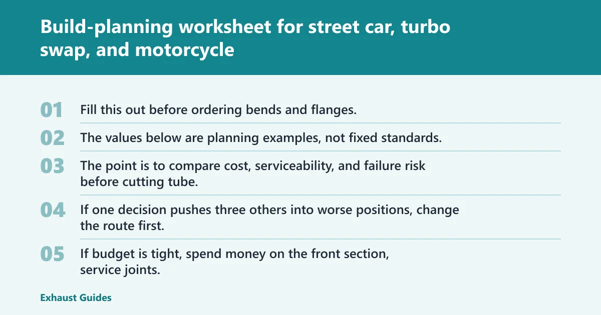
Fill this out before ordering bends and flanges. The values below are planning examples, not fixed standards. The point is to compare cost, serviceability, and failure risk before cutting tube. If one decision pushes three others into worse positions, change the route first, not the clamp catalog.
| Build scenario | Pipe diameter plan | Bend radius plan | Flange style | Joint type plan | Hanger count plan | Flex placement plan | Cost and durability note |
|---|---|---|---|---|---|---|---|
| Street car | Moderate diameter matched to engine output and underbody room; avoid upsizing that crowds axle and floor clearances | Use the largest radius that still clears crossmembers to reduce cut count and ease alignment | Head flange matched to engine outlet; 2-bolt or 3-bolt often practical at front break | Front flange, one mid slip-fit or band-clamp joint, rear clamp or flange for axle-back removal | Support near front pipe mass, mid resonator or catalytic converter, rear muffler | One flex near engine movement zone, ahead of the heaviest unsupported front section | Aluminized or mild steel keeps cost down; stainless costs more but cuts replacement frequency |
| Turbo swap | Diameter set by turbo outlet, power target, and tunnel space; keep enough room for heat control and clamp access | Tighter radius often needed near firewall, rack, and subframe; expect more pieced bends | Turbo outlet flange or V-band at the turbine, service flange or V-band near transmission area | V-band at downpipe if clamp access exists; another removable joint before the tunnel or crossmember | Support soon after downpipe mass, again at mid-pipe, and at rear muffler or merge section | One flex in the front section after the first stable bend and before long chassis-mounted pipe length | 304 stainless is common here because front-section heat and corrosion punish cheap tubing |
| Motorcycle custom | Diameter set by engine layout, stance, and leg/frame clearance; visual balance matters alongside flow | Use U-bends and 45-degree bends with radius chosen for frame wrap and ground clearance | Head flange matched to engine ports; rear service joints used only if needed for removable baffles or muffler sections | Mostly welded sections with one service joint where muffler removal or transport matters | Support near collector or merge and near muffler mass, with clean tab geometry to resist vibration | Use flex only when engine/frame relationship calls for it; many hard-mounted-looking runs still need movement planning | Mild steel is cost-friendly and easy to rework; stainless costs more but reduces rust on exposed tubing |
Decision rules that save money later
If budget is tight, spend money on the front section, service joints, and hangers before spending it on exotic material. A cheap rear section is easier to rebuild than a cracked turbo downpipe with no room to remove it. If the build needs frequent service, pay for better joint strategy first.
Do not use a flex section to hide a route that lacks hanger support. Do not use a V-band where the clamp cannot be reached. Do not weld every joint solid if the gearbox will need to come out through the same tunnel later.
Frequently asked questions
What exhaust pipe material is best for fabrication?
For most home builds, the best material is the one that fits the budget, expected corrosion exposure, and welding skill without forcing bad routing choices. Mild steel is affordable and easy to rework, 304 stainless lasts longer, aluminized steel suits budget street use, and titanium only makes sense when weight savings justify the cost and process demands.
Can you build a custom exhaust without welding?
Yes, a custom exhaust can be built without welding by using slip joints, flanges, and exhaust clamps, but layout freedom, long-term sealing, and vibration resistance are usually worse than a welded system. No-weld builds work best for temporary mockup, simple axle-back sections, or low-stress serviceable joints with good support.
How do you choose exhaust flange sizes and styles?
Choose flange size and style by matching the engine outlet or existing connection first, then checking bolt access, gasket shape, and section-removal needs. A 2-bolt, 3-bolt, or 4-bolt flange can all work well if the flange stays flat, the bolts are reachable, and the joint is placed where future service still makes sense.
How do you join exhaust pipe sections securely?
Join exhaust pipe sections securely by using welded butt joints for permanent sections, V-bands where repeated removal is expected, and slip-fit clamp joints where adjustment or simple service matters. The secure part comes from fit-up and support geometry, not from the joint type alone. Poorly supported joints fail no matter how expensive the hardware is.
How do you build a mandrel bent exhaust?
Build a mandrel bent exhaust by combining straight tube with preformed U-bends and 45-degree bends, then cutting and rotating those pieces to follow the route through the chassis. Mark each joint before tacking, keep the centerline consistent through the run, and choose bend radius based on packaging rather than appearance alone.
How do you install exhaust flex pipe the right way?
Install exhaust flex pipe near the engine or turbo movement zone, not far downstream, and support the pipe on both sides so the flex section only absorbs motion. The nearby hangers must carry system weight. If the flex is carrying a muffler or converter load, the system design is wrong and cracking usually follows.