o2 Sensor vs Air Fuel Ratio Sensor
An upstream sensor is often a wideband air/fuel ratio sensor if it has five or more wires and the live data sits near a commanded stoich target; a narrowband o2 sensor usually has one to four wires and switches through a low-voltage range around 0.1 to 0.9 volts. Misidentifying it wastes money, can lead you down the wrong code path, and can send you after a good part. This guide shows how to tell which sensor you have, read the scan data, and match the replacement to the code.
| Decision factor | o2 sensor | air fuel ratio sensor | Winner |
|---|---|---|---|
| Typical location | Usually downstream, behind the catalytic converter | Usually upstream, ahead of the catalytic converter | air fuel ratio sensor |
| Primary job | Converter monitoring and fuel-trim support | Primary fuel-control feedback | air fuel ratio sensor |
| Live-data behavior | Switches around 0.45 V | Needs scan-tool interpretation; does not behave like a narrowband switch | air fuel ratio sensor |
| Best next test | Scan-tool comparison and converter-efficiency diagnosis | Scan-tool response test, then heater and circuit checks | tie |
What each sensor measures
The o2 sensor and the air fuel ratio sensor both help the engine management system read exhaust oxygen, but they do not report it the same way. The downstream o2 sensor is usually a conventional narrowband sensor, while the upstream air fuel ratio sensor is the engine’s primary fuel-control feedback and sends a wider, more detailed signal.
Where each sensor sits in the exhaust
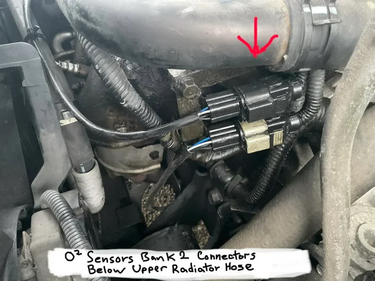
Sensor 1 is usually ahead of the catalytic converter. Sensor 2 is usually behind it. That location matters because the upstream sensor feeds fuel control, while the downstream sensor checks how well the converter cleans exhaust after light-off.
The catalytic converter’s job is emissions reduction. The upstream sensor helps the engine reach closed loop control quickly, and the downstream sensor confirms whether the converter is still doing its job. If you reverse those jobs in diagnosis, you can replace the wrong part and keep the same fault.
How the signal behavior differs
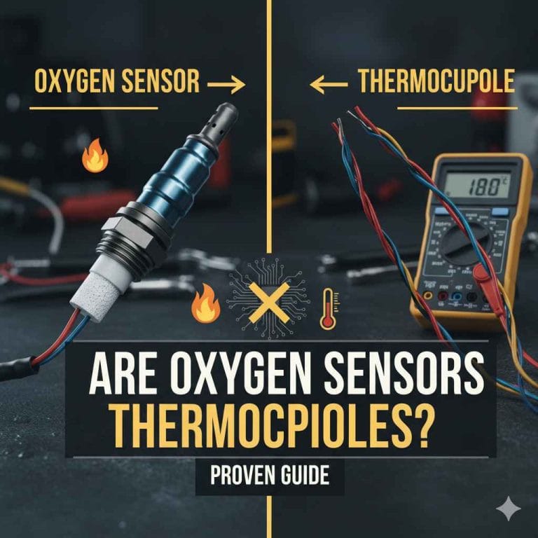
A narrowband o2 sensor swings around 0.45 V, with rich typically near 0.8 volts and lean near 0.2 volts. An air fuel ratio sensor does not give you that same simple switching pattern, so a scan tool must interpret its live data correctly. DENSO also notes that AFR sensors provide a higher level of sensitivity and let the EMS respond more quickly and accurately.
The practical point is simple: a downstream o2 sensor should switch. An upstream AFR sensor should react quickly to changes in fueling, but you should judge it by the scan data the vehicle expects, not by a narrowband-style voltage guess.
Quick sensor comparison matrix
This matrix gives you a fast path from clue to next step. Use it before you buy parts.
| Sensor type | Common location | Code family and likely meaning | Live-data pattern to expect | Next test step |
|---|---|---|---|---|
| o2 sensor | Sensor 2, behind the converter | P013x or P014x style circuit or response fault on the downstream side | Switching around 0.45 V, with rich and lean movement when commanded | Check heater power, ground, and signal wiring; compare downstream switching to upstream activity |
| air fuel ratio sensor | Sensor 1, ahead of the converter | AFR-specific or upstream sensor code, often tied to fuel control or heater fault | Fast response near stoich target, not a simple narrowband swing | Use the scan tool to force rich and lean response, then test heater circuit and wiring |
| Either sensor | Any bank, any side | P0420 with no sensor-specific code | Upstream and downstream data may both look plausible | Do not replace the sensor first; inspect exhaust leaks, converter efficiency, and freeze-frame fuel trims |
How do you tell which sensor your car has?
Check the service information first, then confirm by sensor position and live data. Sensor 1 on many vehicles is a wideband air/fuel ratio sensor, while Sensor 2 is usually a narrowband o2 sensor. The wiring diagram label matters more than the generic word “oxygen” on a parts listing.
Check the service information and engine family
Vehicle families often follow patterns, but not all of them use the same naming. Toyota and Subaru commonly use AFR naming for upstream sensors, while many other makes describe the same upstream wideband role with different terms. Use the exact engine family and model year in the diagram, not a generic catalog description.
Look at Sensor 1 versus Sensor 2 naming
Sensor 1 almost always means the sensor ahead of the catalytic converter. Sensor 2 almost always means the sensor behind it. If the part is upstream and the live data controls fuel trim, treat it as the fuel-control sensor even if the listing uses “O2” language somewhere in the description.
A common first-timer mistake is buying a downstream narrowband sensor because the code includes “oxygen” in the name, then finding the upstream fault is still present. The location and job matter more than the label on the carton.
Confirm with scan-tool live data
Use the scan tool to graph the sensor, then compare it with known-good behavior on the other bank if the engine has one. If the upstream sensor tracks commanded mixture and the downstream sensor switches more lazily, that is normal separation. If both look flat or both look wrong, the problem may be wiring, fuel delivery, exhaust leaks, or a bad sensor.
- Read all codes and freeze-frame data.
- Identify Sensor 1 and Sensor 2 in service data.
- Graph live data on the scan tool.
- Force a rich and lean response.
- Check heater power, ground, and circuit integrity before replacing parts.
How do the signals differ in live data?
Wideband AFR behavior and narrowband o2 behavior are not read the same way. A narrowband downstream sensor should switch around 0.45 V, while the upstream AFR sensor is interpreted through scan-tool data that reflects lambda and fuel correction rather than a simple voltage flip.
Wideband AFR behavior at stoichiometric lambda
DENSO says 14.7 parts air to one part fuel is the most efficient mixture, and that oxygen sensors are commonly referred to as Lambda sensors. In practice, the upstream AFR sensor helps the engine stay near that stoich target in closed loop, and the engine can reach closed loop control much quicker with AFR sensors.
That quick closed-loop entry matters most after cold start. If the sensor is slow, biased, or electrically weak, fuel control can drift before the system settles. That is why upstream live data deserves more attention than a simple go-or-no-go voltage check.
Narrowband o2 switching around 0.45 V
The downstream o2 sensor should switch rich and lean around 0.45 V. The same source notes that rich can read around 0.8 volts and lean around 0.2 volts. If the sensor stays fixed near center, is lazy, or does not move with mixture changes, start by checking circuit power, ground, and exhaust conditions before replacing it.
What rich and lean response should look like
Force a rich condition and watch for a clear response. Then force a lean condition and look for the opposite movement. If the upstream sensor does not react while fuel trim changes, suspect wiring, heater failure, contamination, or a fueling problem rather than assuming the sensor element is bad.
Suppose a 2012 four-cylinder idles rough with fuel trims at +18% and a P0171 code. If the upstream sensor graph stays flat during throttle blips but the heater circuit has no power, start with the circuit, not the sensor body.
What codes point to an AFR sensor problem?
Codes can point to the sensor, the heater circuit, or a problem that only looks like a sensor fault. AFR-specific codes and upstream oxygen sensor codes deserve different treatment, while P0420 usually sends you toward catalyst efficiency diagnosis rather than an upstream sensor replacement.
AFR and o2 sensor code families
P013x and P014x families often point to oxygen sensor circuits or performance on the upstream or downstream side, depending on the exact code and bank. AFR-specific codes point more directly at the upstream fuel-control sensor. Always match the code to the sensor position before ordering anything.
Heater circuit codes
Heater circuit faults are often electrical rather than sensing-element failure. A bad fuse, corroded connector, broken wire, or missing ground can set a heater code even when the sensing element itself is fine. That is why heater testing belongs near the start of diagnosis, not after a parts swap.
When P0420 points away from the sensor
P0420 usually points to catalyst efficiency, not an automatic upstream sensor failure. The converter is monitored by the downstream o2 sensor, so a bad comparison between upstream and downstream activity can flag the converter, the exhaust system, or a fueling issue. Replacing the wrong sensor first can spend money and leave the code in place.
Why upstream and downstream sensors are tested differently
Upstream and downstream sensors are tested differently because they do different jobs and send different signals. The scan tool is the first check for both, but the multimeter is mainly for heater circuit, power, ground, and reference checks, not for proving a wideband sensor by itself.
Scan-tool response tests
For the upstream sensor, use the scan tool to graph live data and force rich and lean response. Compare banks if the engine has more than one bank, or compare against a known-good pattern from the same vehicle family. A good response tells you the sensor is awake; a bad response tells you nothing yet about whether the wiring or the sensor failed.
Heater circuit checks with a multimeter
Use the multimeter for circuit work. Check heater resistance, power feed, ground integrity, and any reference or signal wiring the diagram calls for. If the heater circuit is open or shorted, the sensor may never reach operating temperature, which can distort the live data and set a code on its own.
A bad connector shell at the front bank can create a heater fault on a sensor that still reads reasonably once hot. That is why a good diagnosis separates circuit failure from sensing failure before any replacement decision.
Choose o2 sensor if… / Choose air fuel ratio sensor if…
Choose the o2 sensor when the fault is on Sensor 2, the code points to downstream catalyst monitoring, and the live data should be switching around 0.45 V. Choose the air fuel ratio sensor when the fault is on Sensor 1, the engine uses upstream fuel-control feedback, and the scan tool shows a wideband-style signal that should respond quickly to rich and lean changes.
- Choose o2 sensor if the code and location point to the converter side, the sensor is downstream, or you are chasing catalyst monitoring and downstream switching.
- Choose o2 sensor if live data shows narrowband switching near 0.45 V and the heater circuit checks out.
- Choose air fuel ratio sensor if the problem is on Sensor 1, fuel trims are abnormal, and the vehicle uses upstream wideband feedback for primary control.
- Choose air fuel ratio sensor if the scan tool shows a poor rich/lean response at the upstream sensor and the wiring and heater circuit are verified.
Do not swap sensor types. The same source states these sensors cannot be exchanged, and the guide warns not to bench-test a wideband A/F sensor like an old narrowband sensor. If the wrong part goes in, the code path usually stays wrong too.

- Downstream narrowband layout fits O2 sensor use
- Heated 4-wire design supports winter performance
- Direct replacement with listed OE numbers
Frequently asked questions
Air/fuel ratio sensor vs oxygen sensor
The main difference is job and signal style. An air/fuel ratio sensor is usually the upstream fuel-control sensor, while a narrowband oxygen sensor is usually downstream and switches around 0.45 V. They are not interchangeable, and they require different scan-tool interpretation.
What is air fuel ratio sensor?
An air fuel ratio sensor is the upstream sensor that gives the engine management system its primary fuel-control feedback. It sits ahead of the catalytic converter and helps the system adjust fueling quickly and accurately during closed loop control.
How air fuel ratio sensor works
The sensor reports exhaust mixture near stoich in a way the scan tool can interpret as a wideband signal, not a simple switch. That lets the engine respond more quickly and accurately to rich or lean changes than a narrowband sensor can.
What does air fuel ratio sensor do?
It helps the engine hold the correct mixture, especially during warm-up and closed loop operation. The upstream AFR sensor feeds fuel-control decisions, while the downstream sensor mainly watches catalytic converter performance and supports fuel trim correction.
Can I use an oxygen sensor instead of an air/fuel ratio sensor?
No. The same source states these sensors cannot be exchanged. A narrowband o2 sensor will not provide the same upstream fuel-control signal that the engine expects, so the wrong part can keep the fault active and create new drivability problems.
How do I tell if my car has an AFR sensor or an O2 sensor?
Check the service information, then confirm the sensor location and live data. Sensor 1 is usually upstream and often wideband AFR; Sensor 2 is usually downstream and usually narrowband o2. The scan tool should confirm which signal style the ECU expects.
Why are upstream and downstream sensors tested differently?
They have different jobs and different signal shapes. Upstream testing focuses on fuel-control response and heater circuit integrity, while downstream testing focuses on switching behavior and converter efficiency. The scan tool comes first, then the multimeter for circuit checks.
Can a bad air/fuel ratio sensor cause a check engine light?
Yes. A faulty upstream sensor can set a check engine light through response, circuit, or heater codes, and it can also distort fuel trims enough to trigger mixture-related faults. That said, wiring, exhaust leaks, and fueling problems can cause the same light.
Do wideband sensors and narrowband sensors look the same in live data?
No. A narrowband sensor usually switches around 0.45 V, while a wideband AFR sensor is read through scan-tool data that reflects fuel-control behavior rather than a simple voltage swing. If you read them the same way, you can misdiagnose a good sensor as bad.