Diesel Exhaust System Diagram for Beginners
A beginner diesel exhaust system diagram usually shows about five main flow points, such as the engine outlet, turbo/aftertreatment, DPF, SCR with DEF injector, and tailpipe. Trace exhaust one way and keep DEF supply lines separate. Mixing them up leads to wrong diagnosis and wasted parts. This guide maps each part and shows how to read service diagrams without confusing exhaust flow with DEF supply.
| Layout type | Typical packaging | What you usually see in the diagram | Beginner tip |
|---|---|---|---|
| Light-duty | Compact underbody or cab-adjacent aftertreatment | One combined canister with DOC/DPF/SCR labels close together, short DEF line routing, fewer separated boxes | Use labels first; the housing shape can hide multiple functions |
| Heavy-duty | Longer frame rail packaging with more separation | Distinct DOC/DPF/SCR modules, visible mixer section, longer heated DEF line run, separate DEF tank and pump symbols | Trace the red exhaust path and blue DEF path independently before linking them at the injector |
Diesel exhaust system overview


A diesel exhaust system is often described as having two linked paths. One carries exhaust gas from the engine to the tailpipe. The other carries DEF from a tank to an injector that sprays into the exhaust. They meet in the aftertreatment section, where soot is trapped and NOx is reduced.
Exhaust flow from engine to tailpipe
Follow the exhaust stream first. It leaves the engine, passes through earlier exhaust hardware, then reaches the aftertreatment assembly. In many diagrams, the diesel oxidation catalyst and diesel particulate filter sit in one canister, followed by the SCR section and then the tailpipe. SCR reduces NOx after combustion; the DPF captures soot.
A common beginner mistake is to read every box in a diagram as if it were part of the exhaust stream. The DEF tank, pump, heated lines, injector, and controller are not in the exhaust gas path. They belong to the DEF supply and control path, which feeds the injector.
Separate the exhaust stream from the DEF path
Think of the diagram as two lines that interact. The exhaust line moves hot gas rearward. The DEF line moves fluid forward from the tank to the injector. The controller watches temperature, load, exhaust flow, and NOx readings, then tells the injector how much DEF to spray.
Say your diagram shows a tank symbol on one side and a pipe symbol on the other. The tank symbol belongs to the DEF path, not the exhaust flow. The pipe symbols that sit after the engine and before the tailpipe belong to the exhaust path.
Where DPF and SCR fit in the sequence
The DPF sits in the exhaust stream and traps soot. The SCR sits downstream of the DPF in many layouts and helps convert NOx after DEF has been sprayed, mixed, and broken down into ammonia. Some vehicles place the DPF and SCR in one assembly; they still do separate jobs. (UTI) (EPA)
How do you read the diagram?
Start by finding the engine, then trace arrows toward the tailpipe. Look for canister outlines, sensor icons, and labels such as DPF, SCR, DOC, DEF tank, injector, and NOx sensor. A good diagram separates exhaust flow from DEF supply with different lines, arrows, or callouts.
What arrows and labels usually mean
Arrows on service diagrams usually show flow direction. A thick arrow on the exhaust side points from the engine toward the tailpipe. A thin line to the injector usually shows the DEF feed path. Sensor labels mark where the controller gathers data, not where fluid or gas is stored.
- Find the engine outlet.
- Follow the exhaust arrows rearward.
- Locate the DPF canister or combined aftertreatment box.
- Find the DEF injector just upstream of the SCR catalyst.
- Check for NOx and temperature sensors on both sides of the SCR.
- Trace the DEF line back to the tank and pump.
How to spot aftertreatment boundaries
Aftertreatment boundaries are the edges of the hardware that cleans the exhaust after combustion. On some diagrams, the boundary starts at the diesel oxidation catalyst and ends at the tailpipe. On others, only the DPF and SCR assembly is bracketed. The label set matters more than the canister shape.
Picture a pickup diagram with one large box under the cab. That box may hold the DOC, DPF, and SCR in one housing. A medium-duty or semi-truck diagram may show separate canisters spaced farther apart. The labels still tell you which section does what.
How to tell a combined canister from separate modules
A combined canister groups more than one function into one housing. The diagram may show one shell with multiple internal labels. Separate modules are drawn as two or more housings connected by pipe. Many vehicles use a combined aftertreatment assembly, but others split the DOC, DPF, and SCR into distinct units.
What parts are in the system?
The core parts typically include the engine outlet, DOC, DPF, DEF tank, DEF pump, heated DEF lines, dosing injector, mixing section, SCR catalyst, temperature sensors, NOx sensors, electronic controller, and tailpipe. Not every diagram shows each item with the same level of detail, so location clues matter.
Engine outlet, DOC, DPF, and tailpipe positions
The engine outlet starts the exhaust path. The DOC and DPF are commonly upstream of the SCR section, and the tailpipe ends the path after aftertreatment. The DPF traps soot; the SCR reduces NOx. Keep those functions separate when you read a diagram.
DEF tank, pump, lines, injector, and controller positions
The DEF DEF tank stores diesel exhaust fluid and feeds the dosing system. The tank is often heated in cold weather. The pump pressurizes or supplies DEF to the injector, the heated lines carry it forward, and the controller manages dosing based on load, temperature, and sensor readings.
Heated DEF lines matter because DEF can freeze or form crystals when conditions are cold enough. The system may also delay or reduce dosing when exhaust is too cold, because droplets can form deposits instead of converting cleanly.
Sensors you will see on a service diagram
Temperature sensors measure exhaust heat and help protect the aftertreatment. NOx sensors are often placed upstream and downstream of the SCR so the controller can compare what enters and exits the catalyst. Those readings help detect faults and adjust dosing strategy.
Diesel exhaust flow diagram key
This table is a quick map for the most common labels. Use it to connect position, job, and warning signs. If a diagram uses a different shell layout, the labels still point you to the same functions.
| Component | Position in flow | Primary job | Common diagram label | Beginner warning sign |
|---|---|---|---|---|
| Engine outlet | Start of exhaust path | Sends exhaust out of the engine | Engine outlet, turbo outlet | Exhaust leak noise or soot marks near the outlet |
| Diesel oxidation catalyst | Upstream of the DPF in many layouts | Helps condition exhaust before downstream parts | DOC | Check-engine light with aftertreatment fault history |
| Diesel particulate filter | In the exhaust stream before SCR in many layouts | Traps soot | DPF | Soot loading message or frequent regeneration warnings |
| DEF tank | DEF supply path, not exhaust path | Stores diesel exhaust fluid | DEF tank, reductant tank | Low DEF warning or level sensor fault |
| DEF pump | Between tank and injector | Pressurizes or supplies DEF | DEF pump, reductant pump | Start-countdown warning, no-pressure fault, or dosing fault |
| Heated DEF lines | Tank to injector | Carry DEF and help prevent freezing | Heated lines, supply line | Crystallized residue or temperature-related DEF fault |
| Dosing injector | Sprays into exhaust upstream of SCR | Sprays DEF into the exhaust | DEF injector, dosing injector | Deposit buildup or dosing performance fault |
| Mixing section | Between injector and SCR catalyst | Spreads ammonia evenly | Mixing tube, mixer | Poor conversion or deposit formation |
| SCR catalyst | Downstream of the injector and mixer | Converts much of the NOx into nitrogen and water | SCR, SCR catalyst | NOx efficiency fault or emissions warning |
| Temperature sensors | At key points around aftertreatment | Monitor exhaust heat | Temp sensor, EGT sensor | Temperature plausibility fault or dosing reduction |
| NOx sensors | Before and after SCR in many layouts | Check emissions performance | Nox sensor, upstream NOx, downstream NOx | NOx sensor fault or reduced SCR performance message |
| Electronic controller | Controls the DEF path and logic | Manages dosing and fault detection | ECM, ACM, SCR controller | Dosing disabled, warning lamp, or limp-mode style message |
| Tailpipe | End of exhaust path | Releases cleaned exhaust | Tailpipe, outlet | Visible residue or unusual exhaust odor aftertreatment fault |
What does DEF do in the exhaust?
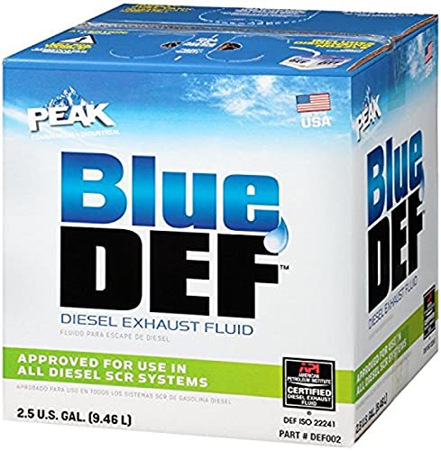
DEF is not fuel, and it does not directly improve mileage. The system injects diesel exhaust fluid into the exhaust after combustion. Heat breaks it down into ammonia, then the SCR catalyst uses that ammonia to convert much of the NOx into nitrogen and water.
How DEF becomes ammonia in hot exhaust
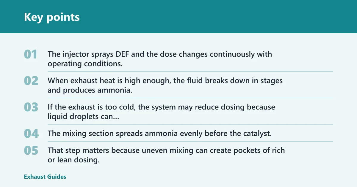
The injector sprays DEF and the dose changes continuously with operating conditions. When exhaust heat is high enough, the fluid breaks down in stages and produces ammonia. If the exhaust is too cold, the system may reduce dosing because liquid droplets can leave deposits instead of reacting cleanly.
Why the mixing section matters
The mixing section spreads ammonia evenly before the catalyst. That step matters because uneven mixing can create pockets of rich or lean dosing, which lowers conversion quality and can leave deposits in the pipe. On a diagram, the mixer sits between the injector and the SCR catalyst.
How the SCR catalyst reduces NOx
The SCR catalyst sits after the mixing section. It treats NOx in the exhaust after combustion and converts much of it into nitrogen and water. The controller uses temperature, load, exhaust flow, and NOx readings to decide how much DEF to inject and when to protect the system.
Where are the DPF and SCR located?
The DPF and SCR are both in the aftertreatment section, but they do different jobs and may sit in the same housing or in separate modules. On many diagrams, the DPF comes first in the exhaust path, then the SCR section, then the tailpipe.
Common pickup layout
Many pickup diagrams show one compact aftertreatment canister under the body. The DOC and DPF may share one shell, and the SCR may sit in the same assembly or just downstream of it. Look for the labels, not just the shape, because the housing can hide several functions.
Common medium-duty and semi-truck layouts
Medium-duty and semi-truck diagrams often spread the parts out more. You may see a separate DPF box, a pipe section with the DEF injector, and a distinct SCR catalyst housing farther back. The DEF tank and pump stay in the DEF supply path, away from exhaust flow.
Why packaging changes from one vehicle to another
Vehicle class, available frame space, and thermal management all affect layout. That is why a pickup, a medium-duty truck, and a semi can use the same basic logic but draw it in different shapes. The diagram labels matter more than the exact canister outline.
Frequently asked questions
How does a diesel exhaust system work?
It carries exhaust from the engine through aftertreatment, then out the tailpipe. The DPF traps soot, while the SCR section uses DEF and a catalyst to reduce NOx after combustion. Sensors and the controller watch temperature and emissions so dosing stays within the system’s needs.
What are the parts of a diesel exhaust system?
The main parts beginners should look for are the engine outlet, DOC, DPF, DEF tank, DEF pump, heated DEF lines, dosing injector, mixing section, SCR catalyst, temperature sensors, NOx sensors, controller, and tailpipe. A service diagram may combine some of these into one housing.
What is the difference between SCR and EGR in diesel engines?
SCR and EGR control NOx in different ways. EGR sends a measured amount of exhaust back into the intake, lowering peak combustion temperature. SCR treats exhaust after combustion by using DEF, ammonia, and a catalyst. They can both reduce NOx, but they work in different places.
How can I read a diesel exhaust system diagram?
Start at the engine outlet and follow exhaust arrows toward the tailpipe. Then find the DEF tank, pump, lines, injector, and controller on the supply side. Use sensor icons and labels to mark what the system is measuring, and use housing boundaries to separate combined canisters from standalone parts.
What happens to DEF in the exhaust
DEF is sprayed into hot exhaust, where it breaks down into ammonia. The mixing section spreads that ammonia before the SCR catalyst. If the exhaust is too cold, the system may delay or reduce dosing because poor atomization can create deposits rather than clean conversion.
Does a diesel exhaust system diagram include sensors?
Yes. Good diagrams usually mark temperature sensors and NOx sensors because the controller depends on those readings. Temperature helps protect the system and shape dosing, while upstream and downstream NOx readings help the controller check SCR performance and detect faults.