Helmholtz Resonator Calculator
A Helmholtz resonator calculator estimates resonant frequency from cavity volume, neck area, neck length, and end corrections. If the measured geometry is off, the final frequency can miss the target by a wide margin. That usually means wasted fabrication, weak drone control, or a resonator that lands on the wrong mode. This guide shows what the calculator computes, how to measure the needed dimensions, and how to verify a design before you cut metal or wood.
How is this calculated?
Press Calculate to see the math with your numbers.
What does a Helmholtz resonator calculator do?
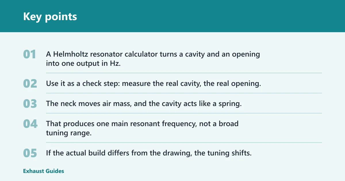

A Helmholtz resonator calculator turns a cavity and an opening into one output in Hz. Use it as a check step: measure the real cavity, the real opening, and the real neck length first, then see whether the design lands near a measured problem frequency before you build.
The core idea is simple. The neck moves air mass, and the cavity acts like a spring. That produces one main resonant frequency, not a broad tuning range. If the actual build differs from the drawing, the tuning shifts.
Where this shows up
In exhaust work, the usual complaint is drone at a narrow road-load frequency. In room acoustics, the usual target is a measured room mode or a bass problem near one peak. A calculator helps both cases, but only if you start from the actual noise peak, not from a guess based on room size or engine RPM alone.
That difference matters because a Helmholtz chamber is different from a quarter-wave or J-pipe resonator. A quarter-wave device uses pipe length to place a standing wave along the tube. A Helmholtz chamber uses cavity volume, opening area, and effective neck length to tune a single resonant peak.
How does a Helmholtz resonator work?
A Helmholtz resonator works as a mass-spring acoustic system. Air in the neck moves back and forth as the mass, and the compressed air in the cavity stores and releases pressure like a spring. Larger cavity volume lowers the frequency; larger neck area raises it.
The resonator responds most strongly near one frequency because the air motion and cavity pressure exchange energy efficiently there. Away from that point, the response drops quickly. That is why these devices are narrow-band tools, not broad absorbers.
What the cavity and opening do
Cavity volume is the largest tuning lever in many builds. More volume lowers the resonant frequency. Neck area, or aperture area, pushes the frequency up because a larger opening contains more moving air mass and couples more easily to the outside air.
If you double the cavity volume while leaving the opening unchanged, the resonance moves lower. If you keep the cavity the same but enlarge the opening diameter, the resonance moves higher. That trend is reliable even when the final value is not exact.
What inputs does the calculator need
The calculator needs three geometry inputs at minimum: cavity volume, neck area or aperture area, and effective neck length. Units matter. Volume may be entered in liters, cubic inches, or cubic feet depending on the tool, while frequency comes out in Hz.
Do not mix nominal dimensions with measured ones unless the calculator explicitly expects them. A 50 mm hole is not the same as a 50 mm port once you include wall thickness, chamfers, or flares. The geometry that matters is the air opening, not the label on the part.
Measurement checks that matter
- Measure the internal cavity volume, not the outside box size.
- Measure the clear opening diameter or area of each neck or port.
- Measure the physical neck length from the cavity wall to the opening plane.
- Account for end correction to get effective neck length.
- Convert units before entering the calculator.
A common first-timer mistake is using outside dimensions for a box that has thick walls. A 20 liter enclosure can read larger on paper if wall thickness is ignored, and that error can lower the predicted frequency when the calculator should have used the smaller internal volume.
How do you calculate resonant frequency?
A commonly used Helmholtz formula uses speed of sound, neck area, cavity volume, and effective neck length. In simple form, frequency rises with larger opening area and falls with larger cavity volume or longer effective neck length. The output is the resonant frequency in Hz.
One common form is:
f = (c / 2π) × √(A / (V × Leff))
Here, f is resonant frequency in Hz, c is speed of sound, A is neck area, V is cavity volume, and Leff is effective neck length. Applied calculators commonly use effective neck length rather than physical neck length alone, and cited speed-of-sound values can vary slightly between tools.
How to read the result
The number you get is the frequency the resonator is most likely to target. It is not a promise. Calctool warns that the model only applies when wavelength is much larger than the resonator dimensions, which is the condition that keeps the lumped-parameter math valid.
For exhaust drone, compare the result with a measured cabin or tailpipe peak, not with engine RPM alone. For room treatment, compare it with a measured room mode. If the peak sits at 63 Hz and the calculator says 59 Hz, that is often close enough to justify a prototype. If it says 34 Hz, the geometry needs a rethink.
End correction and effective neck length
End correction adds the outside air mass that moves with the neck opening. That extra air behaves as part of the neck, so effective neck length is the physical length plus end correction. In practice, this can move tuning more than many builders expect.
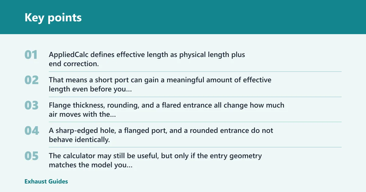
AppliedCalc defines effective length as physical length plus end correction, and gives end correction as 0.6 times radius on each side. That means a short port can gain a meaningful amount of effective length even before you change the visible tube length.
When geometry changes the correction
Flange thickness, rounding, and a flared entrance all change how much air moves with the opening. A sharp-edged hole, a flanged port, and a rounded entrance do not behave identically. The calculator may still be useful, but only if the entry geometry matches the model you are using.
Multiple openings can also stop behaving like one simple neck. If the ports are close together, or if each opening feeds the same cavity differently, the simple single-neck formula can drift. That is one reason a multi-port chamber is best treated as a geometry problem, not a guess.
Picture a 10 liter cavity with a short port and a rounded lip. The rounded lip adds effective length, so the resonant frequency drops compared with the same port cut square. If you ignore that detail, the build may miss the target by enough to matter.
Helmholtz sanity-check examples
This table is a quick check, not a substitute for measurement. It shows the kind of direction you should expect from the input geometry and the most likely error source to inspect before cutting parts.
| Scenario | Input measurements | Calculated tuning direction | Likely error source |
|---|---|---|---|
| Exhaust canister | 22 L cavity, 38 mm port, 120 mm neck | Lower frequency than a smaller canister | Effective neck length from end correction |
| Intake snorkel | 6 L cavity, 45 mm opening, 210 mm neck | Moderate-to-low tuning for intake noise | Measurement of the true cavity volume |
| Single-port bass trap | 1.8 ft³ cavity, 3 in port, 8 in neck | Lower tuning for room mode control | Leakage at seams and panel joints |
| Perforated panel | 0.10 perforation ratio, 4 mm holes, 100 mm cavity | Higher tuning than a larger cavity with same holes | Panel flex and hole count error |
| Bottle-sized demo | 0.75 L cavity, 12 mm neck, 25 mm neck length | Higher frequency, often easy to hear | Open-neck edge shape |
| Leaky box | 12 L cavity, 25 mm port, 70 mm neck | Nominal tuning looks right, real peak weakens | Air leaks reducing resonance depth |
| Rounded port | 9 L cavity, 30 mm flared port, 50 mm neck | Lower than a sharp-edged port of the same length | Rounding changes end correction |
| Multi-port chamber | 16 L cavity, three 18 mm holes, 60 mm neck depth | Depends on combined aperture area | Ports interacting instead of acting as one neck |
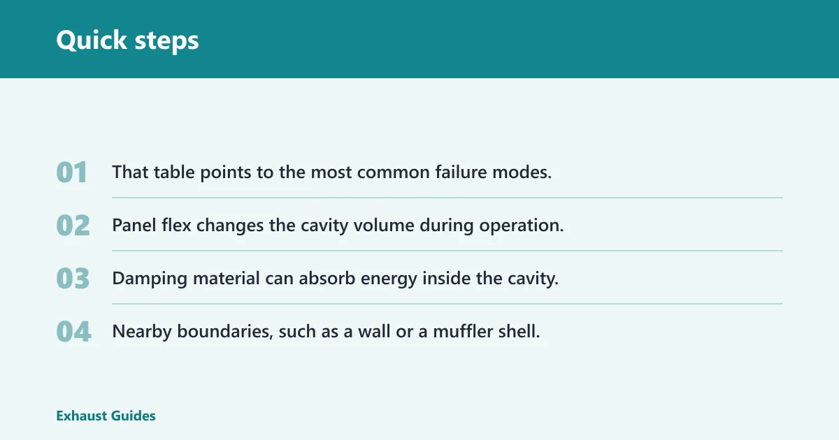
That table points to the most common failure modes. Leakage weakens the peak. Panel flex changes the cavity volume during operation. Damping material can absorb energy inside the cavity. Nearby boundaries, such as a wall or a muffler shell, can shift the measured response once the resonator is mounted.
What frequency should you tune to?
Choose a target from a measured problem frequency whenever possible. For exhaust drone, that usually means the strongest narrow-band drone peak under the driving condition that bothers you. For room treatment, it usually means a measured room mode, not the room’s dimensions alone.
Do not pick one universal frequency for every build. The right target depends on the actual problem. A resonator that works for 90 Hz drone in one car may be useless for a different vehicle, exhaust path, or cabin volume.
Practical target-setting
For exhaust work, separate Helmholtz chambers from quarter-wave devices before you choose a target. A J-pipe uses length to place a wave reflection. A Helmholtz chamber uses cavity and opening geometry to create one tuned resonance. They may both reduce drone, but they are not interchangeable.
For bass traps, use a measured room peak if you can get one. Porous absorbers work broadly, while a Helmholtz-style bass trap is narrow-band. That makes it better for a stubborn peak and less suited to general broadband treatment.
Say your room has a strong 71 Hz mode at the listening position and a porous absorber already handles the midrange. A narrow-band Helmholtz trap tuned near 71 Hz is a better next step than guessing from room size alone.
Frequently asked questions
What is a Helmholtz resonator?
It is an acoustic cavity with a neck or opening that behaves like a mass-spring system and produces one dominant resonant frequency. Builders use it for absorption or tone selection in exhausts, intake systems, and room acoustics. Its shape can be arbitrary, as long as the geometry supports the resonance.
How do you calculate Helmholtz resonator frequency?
Use the standard equation with speed of sound, neck area, cavity volume, and effective neck length. Enter measured geometry, not guessed dimensions, and keep units consistent. The result comes out in Hz, which you then compare with the measured noise peak you want to address.
What is the formula for a Helmholtz resonator?
A common form is f = (c / 2π) × √(A / (V × Leff)). Here, c is speed of sound, A is neck area, V is cavity volume, and Leff is effective neck length. Effective length matters because end correction changes the air mass at the opening.
How do you size a Helmholtz resonator for exhaust drone?
Start with a measured drone frequency from the vehicle under the condition that causes the complaint. Then size the chamber and neck to place the resonator near that peak. Do not confuse this with a quarter-wave or J-pipe setup, which uses a different tuning method and different dimensions.
Why does a real Helmholtz resonator not match the calculator exactly?
Real builds differ because of leakage, wall flex, damping material, boundary effects, and opening geometry. End correction can shift tuning, especially on short necks or rounded ports. The calculator is still useful, but it is best treated as a check against a measured target, not as a promise of exact output.
What is a perforated Helmholtz resonator calculator used for?
It estimates the tuning of a perforated panel absorber that uses the same Helmholtz principle with many holes over a cavity. You enter perforation ratio, hole diameter, panel thickness, and cavity depth. That helps you verify whether the panel is likely to hit the intended narrow-band frequency before fabrication.