
Exhaust Gas Velocity Calculator
Exhaust gas velocity equals flow rate divided by internal cross-sectional area. If the gas is compressible, adjust for actual density, temperature, and pressure too. Skip those corrections and the velocity estimate can be far off, which skews backpressure, heat transfer, and component sizing. This guide shows the formulas, unit checks, and the diameter and gas-condition inputs your calculator needs.
How is this calculated?
Press Calculate to see the math with your numbers.
What exhaust gas velocity means

Exhaust gas velocity is the speed gas moves through a duct, pipe, or stack section. The relationship stays simple: velocity rises as flow rises, and it falls as area grows. That is why a small change in internal diameter can change velocity a lot.
Use consistent units throughout the calculation. A volumetric flow rate in cubic feet per minute needs area in square feet if you want velocity in feet per minute. A flow in cubic meters per second needs area in square meters if you want velocity in meters per second. Mixed units are one of the fastest ways to get a result that looks clean but is wrong.
This number helps when you size a pipe, judge noise risk, estimate backpressure, check capture at a hood, or compare a design against a target range. It also helps when you need to reverse the problem and estimate flow from a measured velocity.
How to think about the inputs
Start with volumetric flow rate and cross-sectional area. For gas work, volumetric flow is often converted to standard conditions first, then adjusted to actual operating conditions if needed. The right choice depends on whether the system is a duct, an engine exhaust, a gas pipe, or a flare or stack.
A common first-timer mistake is using the nominal pipe size instead of the actual internal bore. The nominal size is only a label. The internal diameter sets the area, and area sets velocity.
Which formula should you use?
Use the simplest formula that fits the system. If the gas behaves nearly the same at the measuring point as it does at the reference point, velocity can come straight from volumetric flow divided by area. If pressure or temperature changes matter, convert the flow or density first. If the gas is clearly compressible across the system, include pressure and temperature correction in the calculation basis.
Volumetric flow method
For many duct and pipe checks, the starting formula is:
Velocity = volumetric flow rate ÷ cross-sectional area
If flow is in ft³/min and area is in ft², velocity is in ft/min. If flow is in m³/s and area is in m², velocity is in m/s. This is the cleanest form when the volume rate already matches the conditions at the point you are evaluating.
Mass flow to velocity
If you know mass flow instead of volumetric flow, convert through density first. The relationship is:
Volumetric flow = mass flow ÷ gas density
Then use volumetric flow divided by area. This matters when you know a mass rate from process data or emissions work, but the pipe velocity needs a volume rate at actual conditions.
Compressible gas adjustment
When pressure or temperature changes are significant, adjust with the ideal gas equation, PV = nRT. GHGSat says changes for different temperature or pressure can be calculated with PV=nRT, and it lists the gas constant as 8.31446261815324. GHGSat also states methane density used is 0.657 kg/m3 at 25 C and 1 atm.
That density figure is only a reference point. Different temperature or pressure changes the density, which changes the velocity you calculate from the same mass flow. In simple terms, lower density means more volume for the same mass, and that usually means higher velocity for the same area.
How do you get the right diameter?
Use the actual internal diameter, not the nominal size on a pipe schedule or parts listing. Then compute area from that diameter. For a round duct or pipe, area comes from the bore the gas actually sees, not the label stamped on the product.
Area from diameter
For a round section, the area is:
Area = π × (inside diameter ÷ 2)²
That square term is why velocity changes sharply with diameter. A modest reduction in bore can push velocity up much more than a casual estimate suggests.
Say your duct changes from 4 in to 3.5 in inside diameter while flow stays fixed. The area drops by more than the diameter change alone implies, so velocity rises faster than many users expect. That can help capture in one case and create noise or backpressure in another.
Why small diameter errors change velocity fast
Because area depends on diameter squared, a small measurement mistake can move the answer a lot. If the true bore is about 10 percent smaller than the nominal assumption, the area is about 19 percent smaller. That same flow then produces a much higher velocity than the calculator first showed.
When do temperature and pressure matter?
Temperature and pressure matter whenever the gas volume at the point of use differs from the reference condition. Standard temperature and pressure are needed when flow is reported at a standard basis, and GHGSat notes that standard temperature and pressure for gas varies by code. The same source says metric standard temperature is 15 C and English standard temperature is 60 F.
Standard conditions versus actual conditions
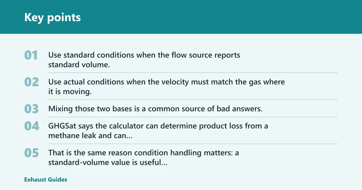
Use standard conditions when the flow source reports standard volume, such as standard cubic feet per minute or standard cubic meters per hour. Use actual conditions when the velocity must match the gas where it is moving, such as inside a hot exhaust pipe or a pressure-changed gas line. Mixing those two bases is a common source of bad answers.
The same source says the calculator can determine product loss from a methane leak and can convert emissions units. That is the same reason condition handling matters: a standard-volume value is useful only if you convert it to the condition basis that matches the pipe or duct.
Using the ideal gas equation
The ideal gas equation gives the adjustment basis for temperature and pressure changes. For many engineering checks, it is enough to convert between standard and actual conditions when the gas is not near extreme pressure or temperature. If the process is more demanding, a real-gas method may be needed, but the key first step is still matching the condition basis to the system.
| Scenario | Correct method | Required inputs | Compressibility matters? | Use standard or actual conditions? | Main mistake to avoid |
|---|---|---|---|---|---|
| Automotive exhaust | Velocity from actual volumetric flow and true inside diameter | Flow rate, inside diameter, gas temperature, pressure if correcting from standard volume | Often yes near hot, fast-flowing sections | Actual at the pipe section unless flow is already corrected to that state | Using raw cam-card numbers as if they were exhaust flow, or using nominal tube size |
| HVAC and local exhaust ventilation | Volumetric flow divided by area | Captured flow, duct inside diameter, hood or branch losses if checking system behavior | Usually low to moderate, but temperature can still shift density | Actual at the duct section if possible; standard only for source reporting | Using standard flow units at the duct without conversion |
| Natural-gas pipe | Mass flow to density to velocity, or standard flow converted to actual volume | Flow, pressure, temperature, gas composition, inside diameter | Yes | Actual line conditions for velocity in the pipe | Using standard cubic feet per minute as if it were actual flow |
| Flare and exhaust stack | Compressible-gas adjusted velocity with actual density | Flow, stack diameter, temperature, pressure, gas density | Yes, strongly in many cases | Actual stack conditions | Skipping pressure correction and underestimating outlet speed |
How to calculate flow from velocity
Reverse calculation is useful when you already know a velocity target or a measured velocity. Multiply velocity by area to recover volumetric flow, then convert to standard or mass flow if the report needs that basis. This is the same relationship turned around.
Back-calculating volumetric flow
Volumetric flow = velocity × cross-sectional area
If a duct velocity is known from a measurement or a design target, this gives the flow the system is moving at that section. From there, you can compare it with fan capacity, engine exhaust demand, or pipe loading.
Mass flow from density
Once you have volumetric flow, mass flow is:
Mass flow = volumetric flow × gas density
That step is essential when you need emission rates or process mass balance. If density changes with temperature or pressure, use the density at the actual conditions, not a reference value from a table.
Checking the result against system limits
Velocity is not a goal by itself. Too low can weaken capture in a hood or let solids settle in a line. Too high can create noise, pressure drop, erosion, or poor control at fittings and outlets. The acceptable range depends on the system type, not on a single universal number.
Picture a 6 in exhaust duct that looks acceptable on paper because the flow is right, but the internal bore is reduced by liner thickness and a coupling. If the area is smaller than expected, the velocity rises and the pressure drop can climb enough to change fan performance.
Header sizing inputs for engine exhaust
Automotive exhaust sizing uses the same flow-over-area idea, but header tuning adds engine timing terms that are not the same as plain pipe flow. AxisCalc says the tool converts target RPM, exhaust valve opening, and cylinder volume into tuned dimensions. It also shows exhaust duration is 235 degrees in the example output and gives a sample primary pipe length of 30.29 in.
Exhaust valve opening and exhaust duration
Exhaust valve opening, or EVO, is given in degrees before bottom dead center. The same source notes typical performance cams open exhaust valves 45-75 degrees BBDC. In the tuning convention used there, exhaust duration is typically computed as 180 degrees plus EVO. That is a formula input, not the same thing as raw cam-card duration.
This distinction matters because header formulas use a timing convention tied to the tuning method. If you feed in the wrong duration definition, the primary length estimate will be off even if the pipe diameter is correct.
Primary tube length
Primary tube length is measured from the head flange to the collector. It is not the same as the total bent length of the header. In tuning formulas, primary length depends on RPM and the exhaust duration term, so the answer changes with the engine setup and not just with tube diameter.
Collector dimensions
Collector dimensions are usually a starting point, not a fixed answer. Collector length and inside diameter are often set as multiples of the primary dimensions, then refined for packaging, pulse timing, and the rest of the exhaust system. If you size only the tube and ignore the collector, the result can miss the intended behavior.
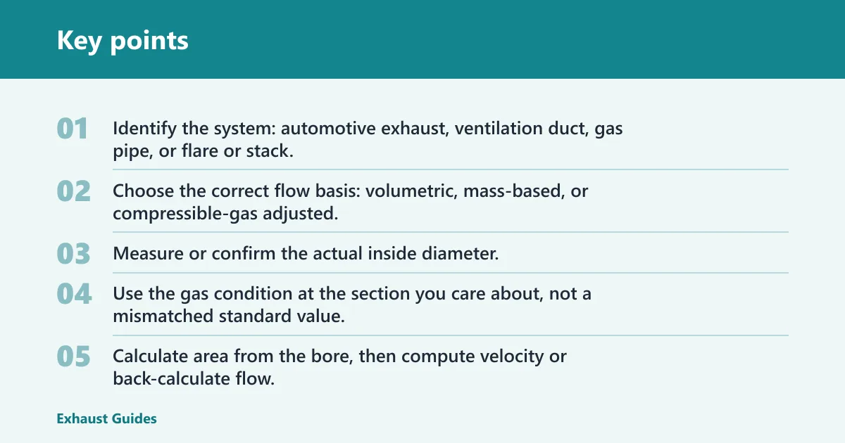
- Identify the system: automotive exhaust, ventilation duct, gas pipe, or flare or stack.
- Choose the correct flow basis: volumetric, mass-based, or compressible-gas adjusted.
- Measure or confirm the actual inside diameter.
- Use the gas condition at the section you care about, not a mismatched standard value.
- Calculate area from the bore, then compute velocity or back-calculate flow.
- Check the result against noise, backpressure, capture, or control limits for that system.
Frequently asked questions
What is exhaust velocity?
Exhaust velocity is the speed at which gas moves through a pipe, duct, or stack section. It comes from flow per unit area, so a smaller bore raises velocity for the same flow. In compressible systems, temperature, pressure, and density can shift the answer enough that a standard-volume value is not enough on its own.
How to calculate exhaust flow
To calculate exhaust flow from velocity, multiply the gas velocity by the cross-sectional area of the passage. If you need mass flow, multiply the volumetric flow by gas density at the actual conditions. This is the same relationship used in reverse for velocity calculations, and it is useful when sizing or checking a known duct speed.
How do I calculate gas velocity in a pipe?
Use the pipe’s actual inside diameter to compute area, then divide volumetric flow by that area. If the pipe carries a compressible gas, adjust the flow or density for the operating temperature and pressure before calculating. Using nominal size or a standard-volume flow without conversion is one of the most common errors.
What formula do I use for gas velocity?
The core formula is velocity equals volumetric flow rate divided by cross-sectional area. For gas systems with pressure or temperature changes, use the ideal gas equation, PV = nRT, as the correction basis when converting between standard and actual conditions. If you already have mass flow, convert it through density first.
What is the recommended exhaust duct velocity?
There is no single recommended exhaust duct velocity for every system. Ventilation ducts, engine exhaust, gas piping, and flare stacks all have different limits and goals. The right target depends on capture, noise, backpressure, erosion, and control. Use the system type first, then check the acceptable range for that application.
How do I size an exhaust pipe for velocity?
Choose the flow you need to carry, decide the target velocity for that specific system, and solve for area. Then convert area to internal diameter. Use the actual bore, not nominal pipe size, and confirm whether the flow is at standard or actual conditions before finalizing the diameter.